A common mistake novice circuit designers make is not adding a current-limiting resistor when using an LED. When using low voltages around 3 volts the LED may not immediately break but it will shorten the life of the LED. This may not seem like a big deal if you are just making a prototype but it is not a good practice to use an LED without a resistor. Also if the current is high the resistors can go over their power rating which can cause the resistor to break and even catch on fire.
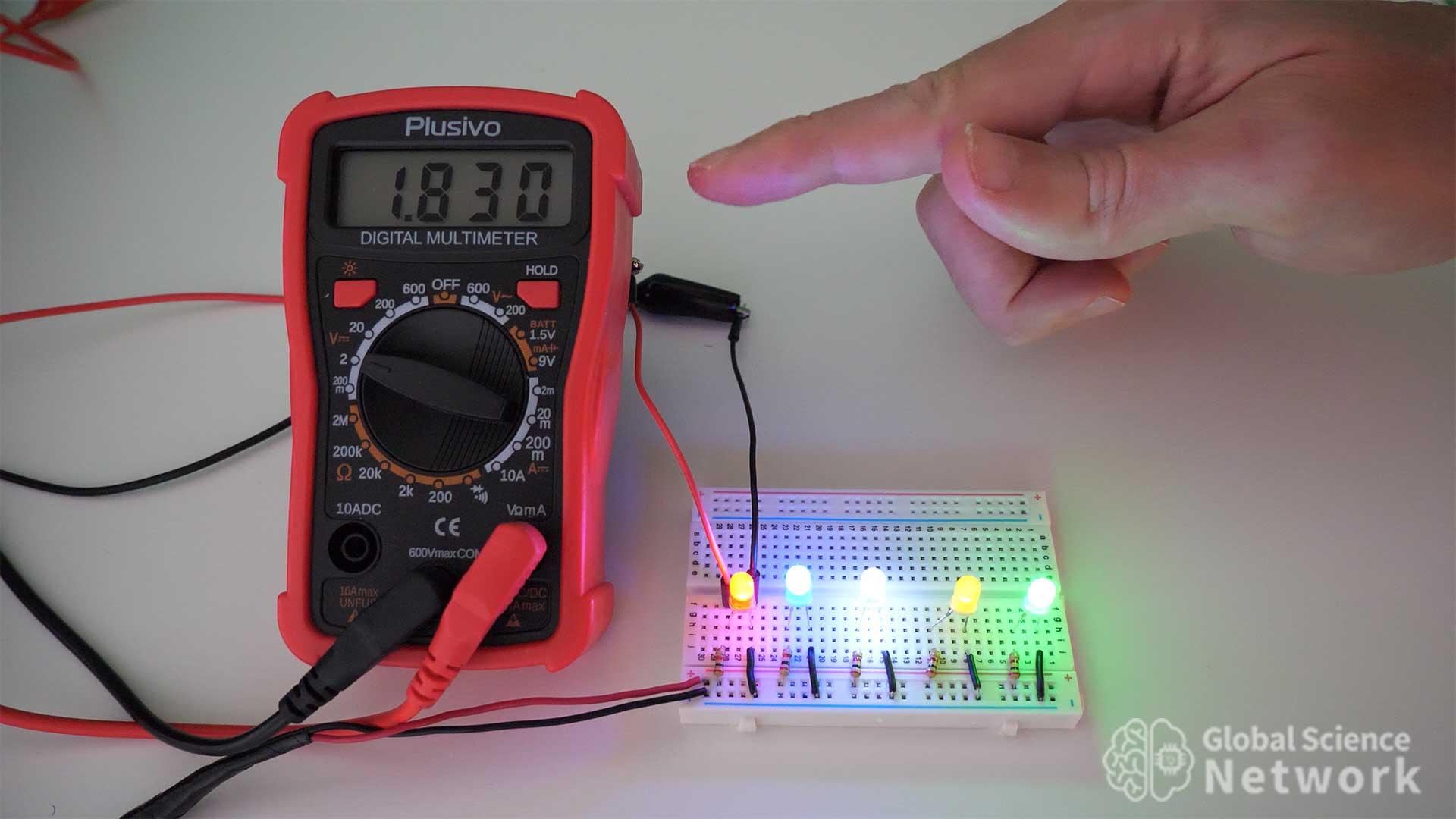
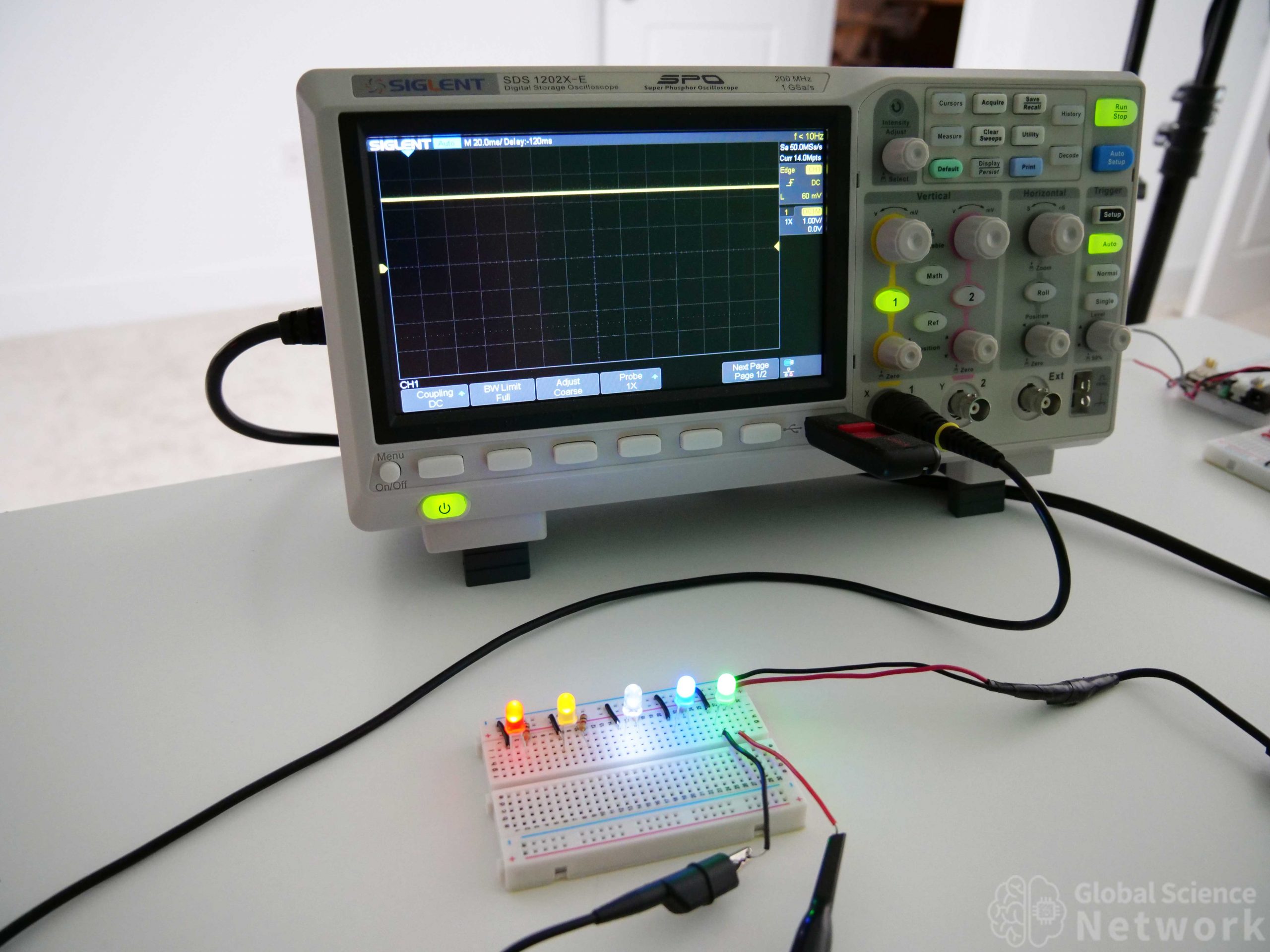
In the photo is a circuit that I built with 5 yellow LEDs each with resistors that have different values. The circuit is powered with 5 volts which means that the current limiting resistor should be 150 ohms or higher. This ensures that the max current will not exceed 20mA. The resistor values used are 300 ohms, 1K, 2K 10K, and 100K. The voltage drop across each LED is the same and is around 1.9 volts. However, the current is lower as the resistance increases. When there is less current flowing across the LED it will be less bright. A super bright LED is not always the goal. Often times it is just an indicator light and using less power is advantageous.
The video above provides a detailed discussion of current limiting resistor values for LEDs. The forward voltage drops are shown on a multimeter.
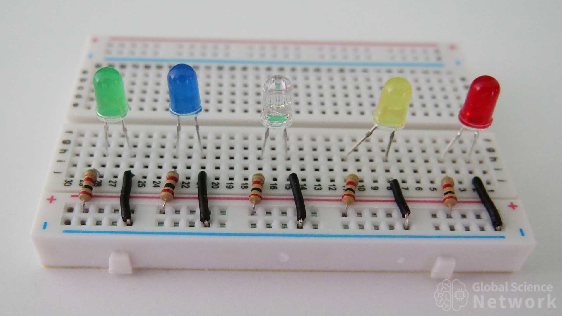
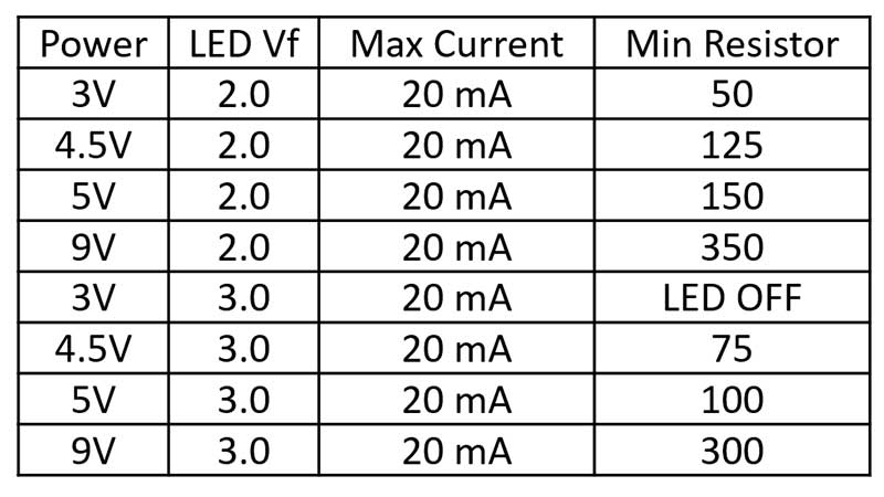
The photo above shows a green, blue, white, yellow, and red LED on a breadboard. Black ground wires are connected to the negative terminals of the LEDs which is also called the cathode. This is the shorter of the two terminals which allows for the polarity to be determined. The positive side of the LED is connected to the positive terminal of the breadboard by going across a 2K resistor. These LEDs are all connected in parallel.
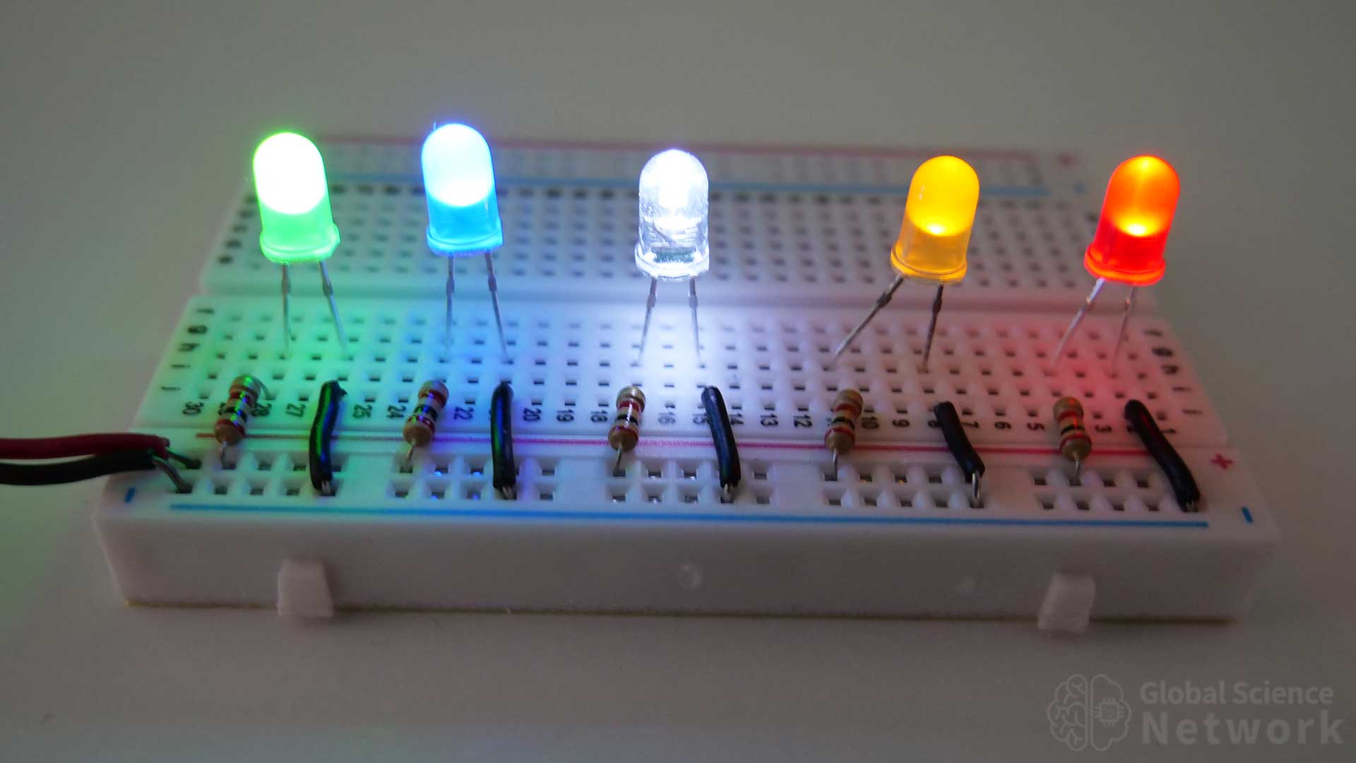
When the LEDs are on they emit different colors of light. This is not just because the plastic or glass case is that color. The photons being emitted are of specific wavelengths based on the semiconductor materials within the LED. The voltage drop across each color LED is going to be different for the same reason. Because the voltage drop is different the current going across each LED is going to be different even though the same current limiting resistor and power supply voltage is used.
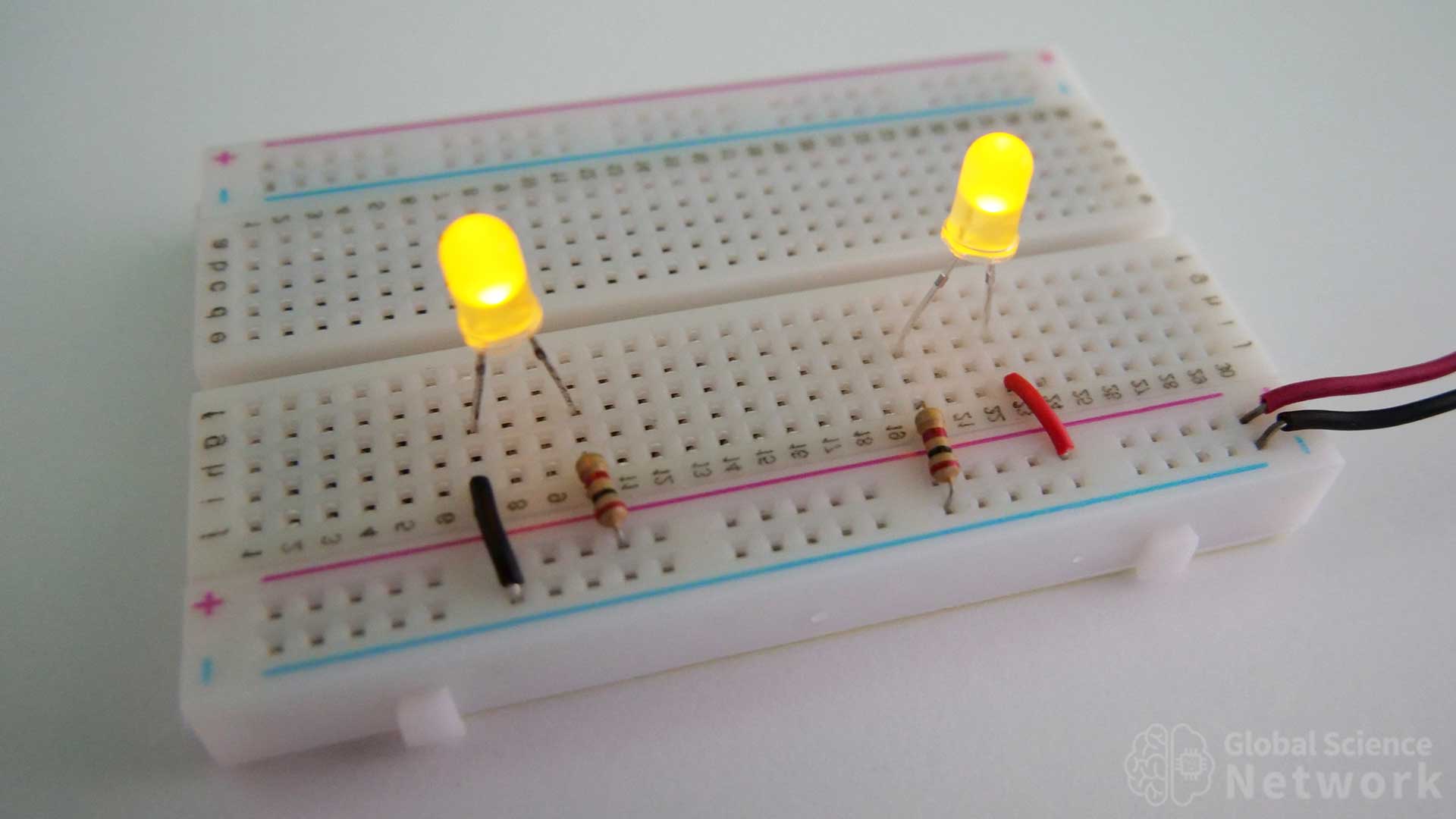
A common question when placing an LED on a breadboard is should the resistor be placed before or after the LED. On the left, a 2K resistor goes from positive 5 volts to the positive side of the LED. The negative side is connected to the ground. In the second case on the right a red wire connects the positive side of the LED and the 2K resistor finishes the circuit by connecting to the ground. In this case, it may seem like 5 volts are going into the LED so it is going to break. However, the location of the LED does not actually matter. In both cases, the voltage drop across the resistor and LED is the same. I prefer to wire-up circuits how it is wired on the left. This is because if the wire or terminal before the resistor were to short there would be nothing to limit the current and would be more likely to cause issues.
LEDs typically come with three ratings. First is the max current rating, next is the forward voltage drop, and last is the light luminous intensity value, in this case, measured in millicandela (mcd). This intensity value can be converted to a luminous flux value in lumens when the beam angle is also supplied. A typical beam width for an LED is 50 degrees so 3000mcd would be 1.77 lumens. Current limiting resistor values can significantly change the brightness of the light. The equation below can be used to find the lowest resistor value that can be used to stay below the max current.
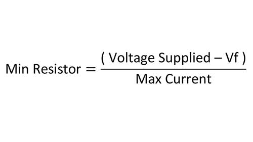
The minimum resistor value will allow for the brightest LED while not exceeding the max current. Typical supply voltages are 3 volts, 4.5 volts, 5 volts, or 9 volts for breadboard circuits. This is because multiple 1.5-volt batteries, USB power, or 9-volt batteries are used as the power source. The forward voltage drop is the voltage drop of the LED. This can be easily measured with an oscilloscope or multimeter. It is a property of the LED material and is a fixed value for a particular LED. Most LEDs have a voltage drop in the range of 1.8-3.2 volts. Regular diodes have a voltage drop of around 0.6-0.7 volts. A common mistake is to think that LEDs also have this lower forward voltage drop.
The table above shows minimum resistor values in ohms for common supply voltages, LED voltage drops, and max current levels. For example, a circuit powered with 5 volts, using a yellow LED with a forward voltage drop of 2.0 volts requires a minimum resistor value of 150 ohms. The exact voltage drop may vary but this gives a value close to what is required. I measured the voltage drop of a yellow LED to be 1.9 volts. This would make the actual min resistor value 155 ohms.
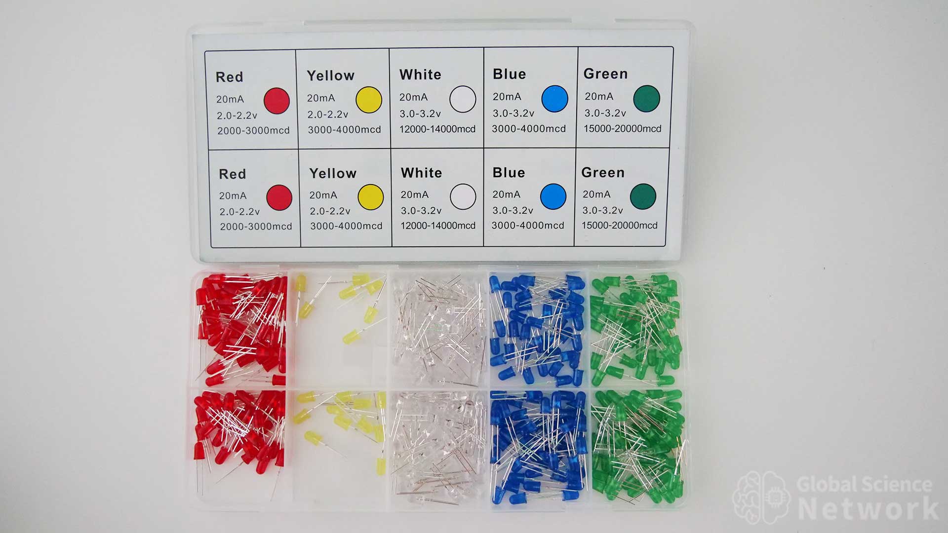
Yellow and red LEDs have voltage drop values close to 2.0 volts. White and blue LEDs have voltage drop values close to 3.0 volts. So the table is helpful in selecting the proper resistor value to stay within the max current limits.
Resistors have max power dissipation ratings. A common rating is 0.25 watts plus or minus 5 percent. For our example, the power across the resistor would be 3 volts times 0.02 Amps using a 150-ohm resistor and yellow LED. The power dissipated by the resistor is 0.06 watts which is 60 milliwatts. This means the LED is limiting the max power more so then the resistor. When using higher voltages it is important to track the power dissipation across the resistor for two reasons. First, it can exceed the rated values causing damage to the resistor, which could possibly cause a fire. Secondly, this is wasted power that is dissipated as waste heat across the resistor.
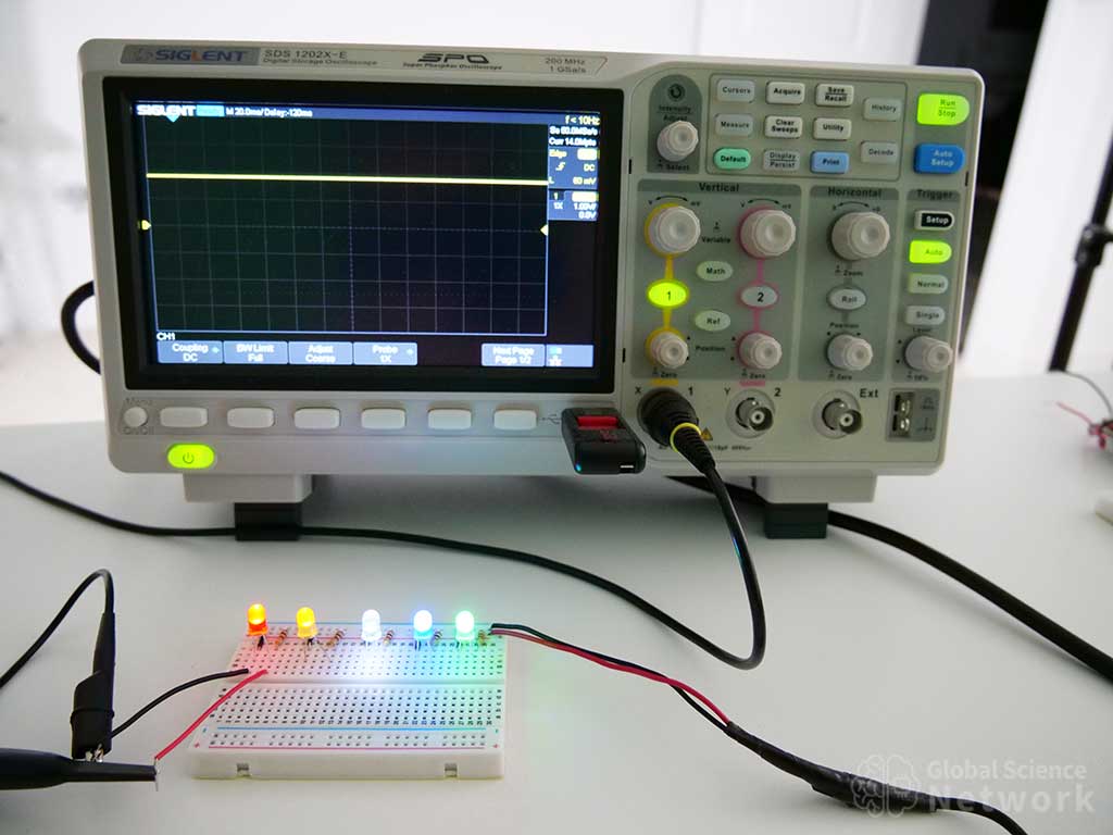
The oscilloscope shows a voltage drop of 1.9 volts for a red LED. It is rated to have a voltage drop from 2.0-2.2 volts. The current limiting resistor value in this case is 155 ohms. In the photo, a 2K resistor is used and the LED is still very bright. It is important to note that the forward voltage drop will vary based on the supply voltage and resistor value used. In this example the supply voltage is 5 Volts and the resistor is 2,000 Ohms.
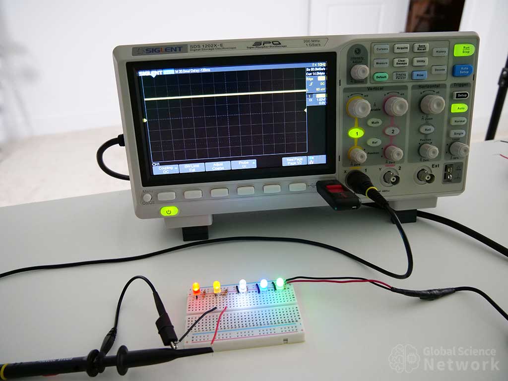
The oscilloscope shows a voltage drop of 1.9 volts for a yellow LED. It is rated to have a voltage drop from 2.0-2.2 volts. The 1.9-volt forward voltage drop would mean the minimum resistor value used should be 155 ohms. A 2K resistor is used in the photo. Yellow is my preferred LED color to use when using breadboards and the 2K resistor makes it the perfect brightness for circuit demonstration purposes.
The oscilloscope shows a voltage drop of 2.8 volts for a white LED. It is rated to have a voltage drop from 3.0-3.2 volts. Using the actual forward voltage drop the minimum resistor value is 110 ohms. White LEDs are very bright and are good options when providing light is the intended purpose of the led.
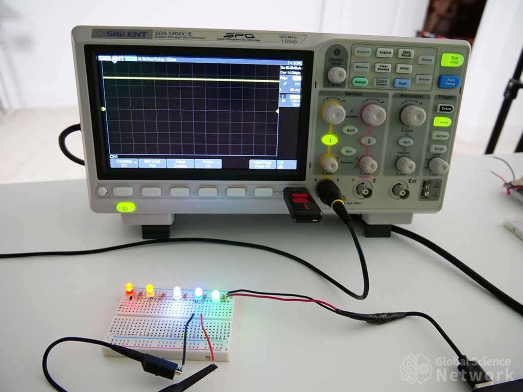
The oscilloscope shows a voltage drop of 2.7 volts for a blue LED. It is rated to have a voltage drop from 3.0-3.2 volts. Since the actual voltage drop is 2.7 volts the minimum resistor value is 155 ohms.
The oscilloscope shows a voltage drop of 2.3 volts for a red LED. It is rated to have a voltage drop from 3.0-3.2 volts. This is 0.7 volts different than its expected rated value. When using components it is always good to test their actual performance values. Green LEDs can have a voltage drop level from 2-3.2 volts. Now that we know the actual forward voltage drop is 2.3 volts we can calculate the minimum resistor value which is 135 ohms.
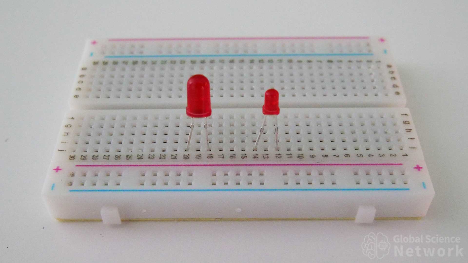
On the left is a 5mm red LED and on the right is a 3mm red LED. These are the two most common LED sizes that are used on breadboards. Even though they are different sizes they actually have the same forward voltage drop and max current rating. The difference is in the light intensity values. For example, the 5mm red LED provides 2,000-3,000mcd while the 3mm LED provides 1,000-2,000mcd. It is important to note that each LED actually lets off the same amount of light, the difference in intensity is from the beam width of the LED.

Cody started the Global Science Network with the idea people should be focusing more time, energy, and resources on useful projects. He has a bachelor’s degree in aerospace engineering and a master’s degree in mechanical engineering. Cody has worked for the US federal government, a university, a large corporation, small businesses, and for himself. He has done human brain computer interface research and is currently working towards creating non-biological human consciousness.