Building a 4-bit calculator using individual transistors helps demonstrate how computers add numbers. This can be thought of as a simple arithmetic logic unit (ALU) for a computer. In this case, the calculator is a stand-alone device that can add two 4-bit inputs together. In binary, the highest 4-bit input is 15 which is 1111 in binary. There is also a carry-in slot in the first full adder so the calculator can add 15+15+1 for a max value of 31 which is 11111 in binary.
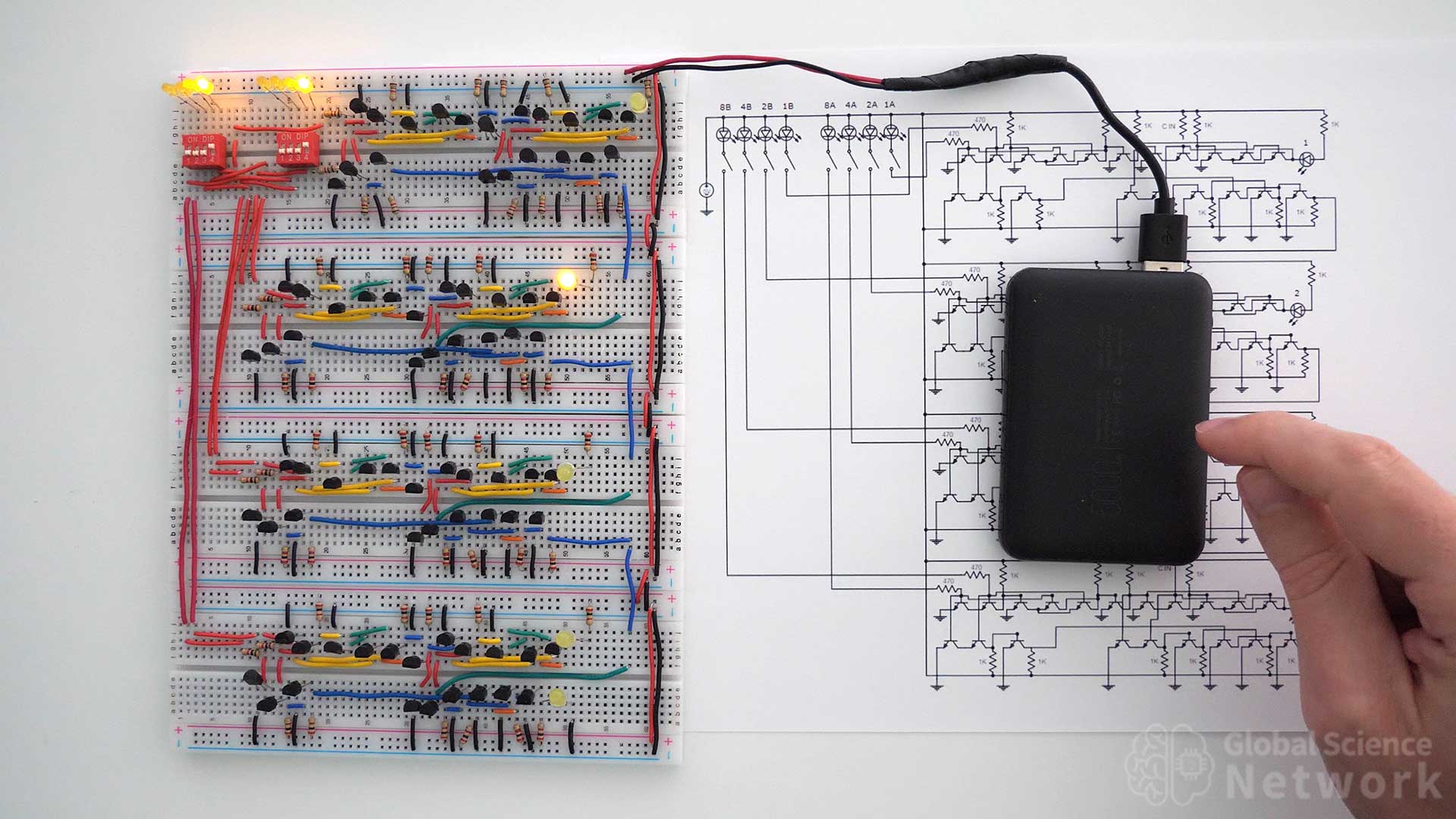
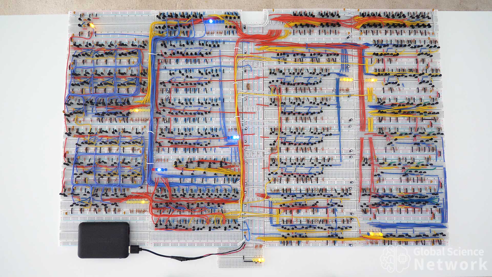
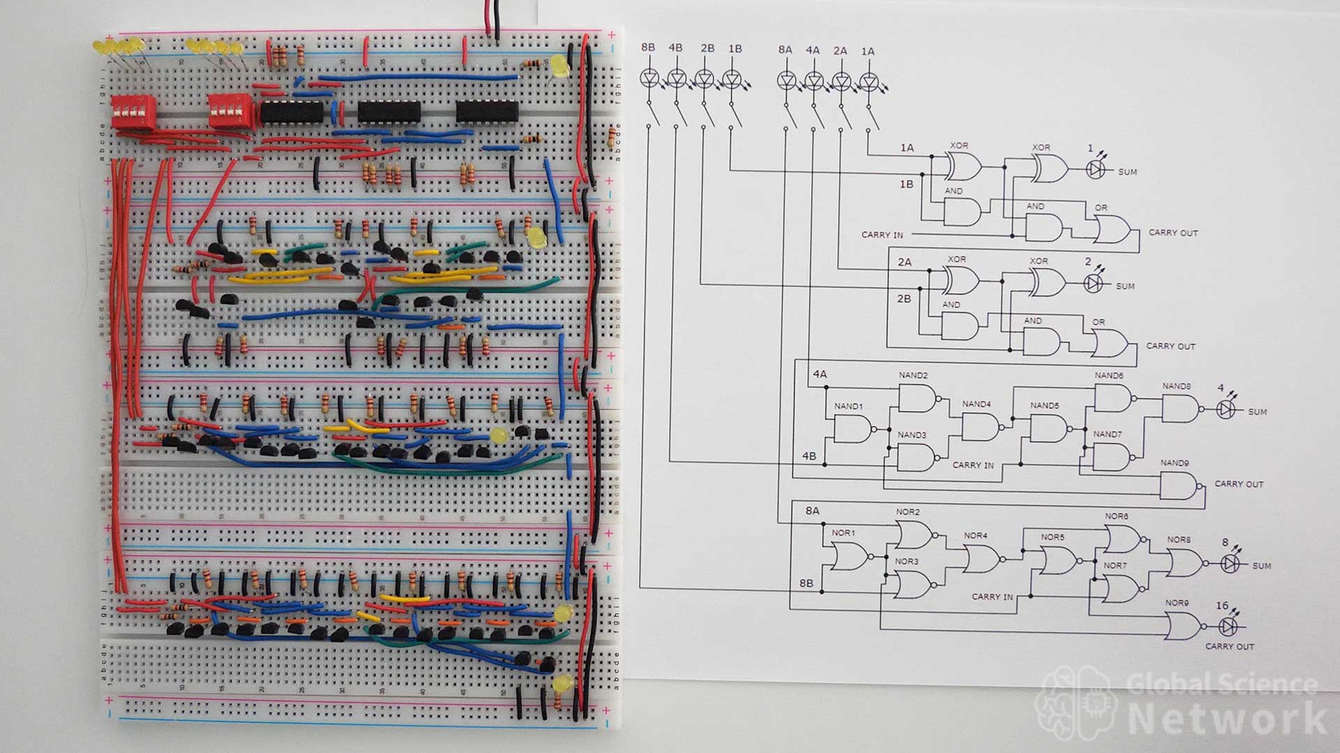
The photo above shows the 4-bit calculator I built on four breadboards. Two 4-slot dip switches control whether the inputs are on or off. When an input is on the dip switch will be in the up position and the LED above the dip switch will be on. When an input is off the dip switch will be in the down position and the LED above the dip switch will be off. The output is represented by the 5 LED lights on the right-hand side of the breadboard. The position of the LED determines its value. When the top LED is on it represents 1, the second LED represents 2, the third LED represents 4, the fourth LED represents 8, and the fifth LED represents 16. If all 5 LEDs are on it is 11111 in binary which is 15 in the base 10 number system.
4-Bit Calculators
In this article, I am going to show two different ways to build a 4-bit calculator. The first is going to use 4 full adders that are all built the same way. Next, I am going to show how to use 4 full adders which are all built differently to build a second 4-bit calculator. This will help demonstrate that there are multiple ways to design digital logic gate circuits that perform the same operation. Building a 4-bit calculator would be a fun circuit science project for someone looking to further their understanding of digital logic gates. I plan to take the first 4-bit calculator and used it as an ALU for a 4-bit computer that is built with individual transistors.
The video above shows how to build the first 4-bit calculator using individual transistors. It also explains the binary number system to describe how the calculator adds in base 2. At the end of the video the calculator is tested by varying the two 4-bit inputs and it works as expected. The calculator is powered by a 5-volt battery pack that is typically used to charge cell phones.
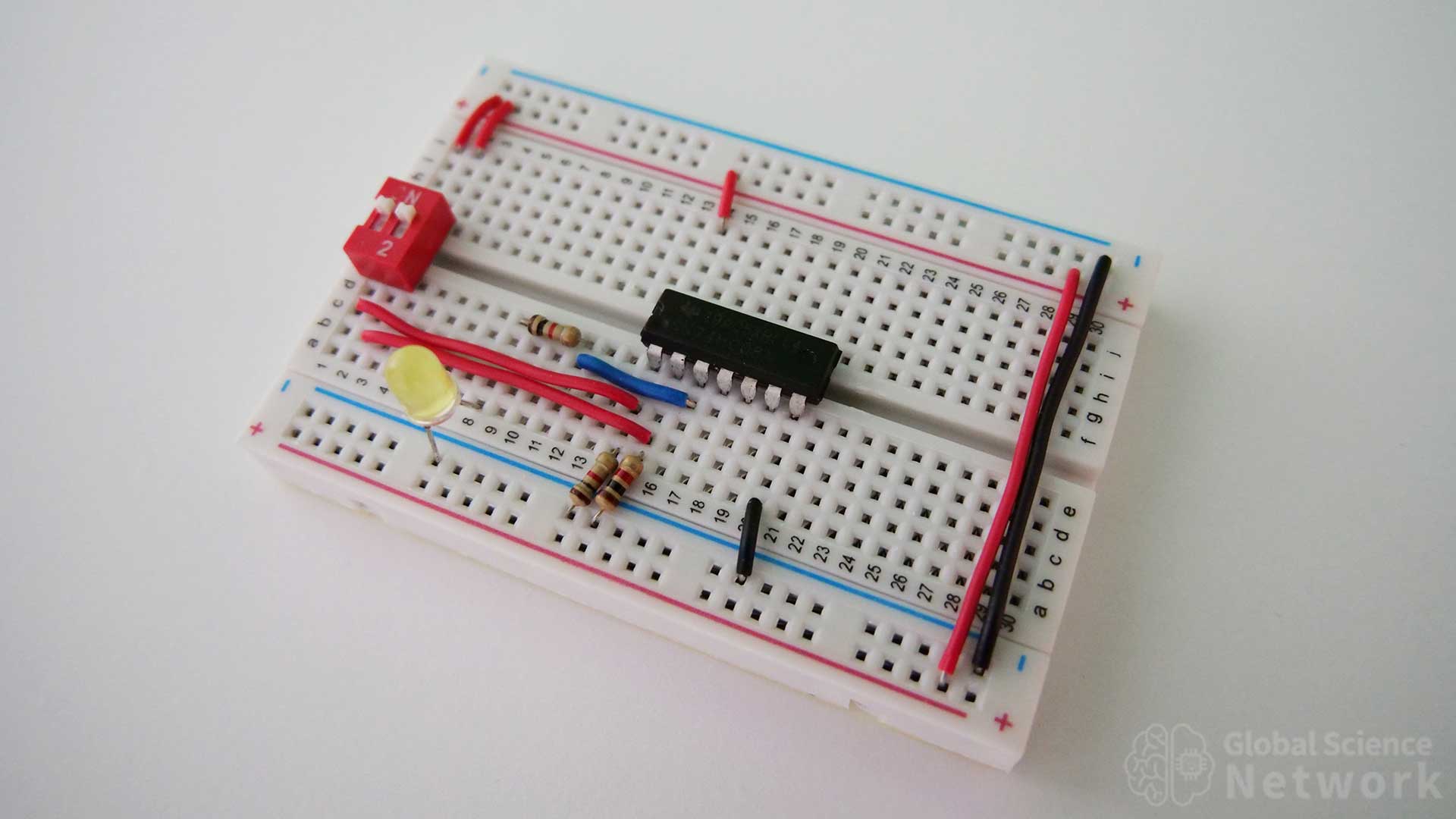
4-Bit Calculator Built with Individual Transistors
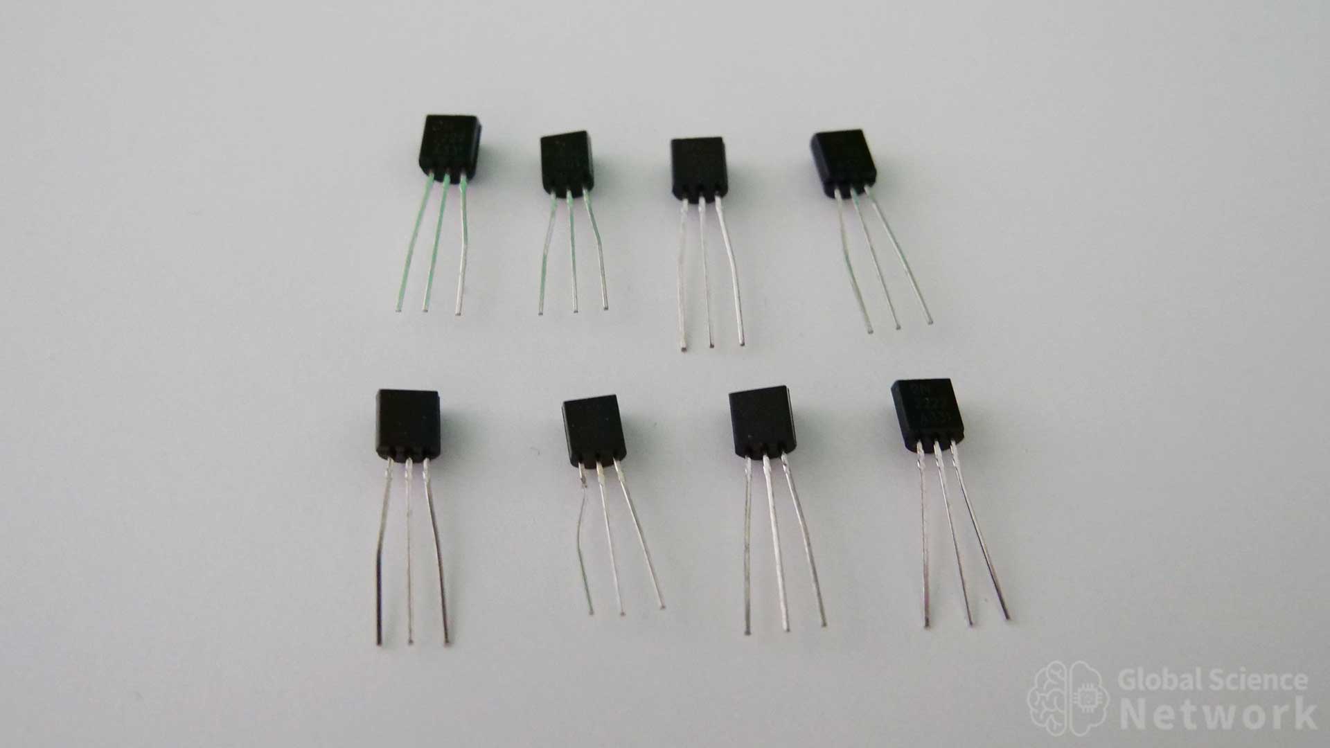
The first 4-bit calculator is shown above. There are four breadboards that are connected together. Each breadboard has one full adder. The first full adder also has dip switches to turn the inputs on or off. All of the resistor values used are 2K. On the left side of the calculator red wires run from the top positive 5-volt rail to inputs A and B of each full adder. The carry-out of full adder 1, full adder 2, and full adder 3 feed into the carry-in location in the next full adder. On the right-hand side, red and black wires connect power to each breadboard. The main power is supplied to the top breadboard from the two wires on the top right-hand side of the calculator. All of the transistors used are NPN type with a model number of 2N2222, and model number 2N3904 will also work as these have very similar properties.
In the photo the first 4 inputs are on, the second 4 inputs are on and the carry-in is off. This means that 1111 + 1111 + 0 is what is being added. The output should therefore equal 30 which is 11110 in binary. If you look at a calculator you can see that the LED lights show an output of 11110 as expected.
Logic Gate Level Circut Diagram
The logic gate-level circuit diagram is shown above. Each full adder is built with 2 XOR gates, 2 AND gates, and an OR gate. The inputs are in the top left corner of the circuit while the outputs are on the right-hand side of each full adder. Inputs are labeled based on their value for example input 4A has a value of 4 based on its position in the circuit. This diagram provides a high-level design of how the 4-bit calculator should be built. It does not however detail how each logic gate is to be built.
Component Level Circut Diagram
The component-level circuit diagram for the 4-bit calculator is shown above. This shows how each logic gate is to be wired using individual transistors. Each full adder is built the same way. So once it is understood how to build one full adder it is not difficult to wire four of them together to form the adder circuit. In each full adder, the first 6 transistors are the first XOR gate, and the next 5 transistors are the second XOR gate. The second XOR gate does not send an output so one less transistor is needed. In the bottom row of each full adder, the first three transistors are the first AND gate, the next three are the second AND gate. Finally, the last three transistors are the OR gate.
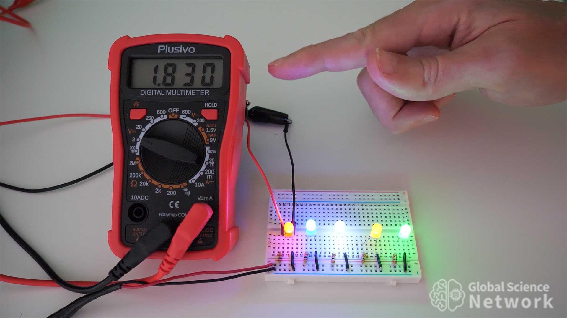
All resistor values are labeled 1K except the input resistors which are 470 ohms. The input resistors are lower because the inputs have a 1.9-volt voltage drop across the input LEDs being used to show if the input is on or off. The carry-in on the first full adder is turned on by connecting the second input of the second AND gate to the 5-volt rail. This is done by adding a resistor to the carry-in location.
4-Bit Calculator Built with Different Types of Logic Gates
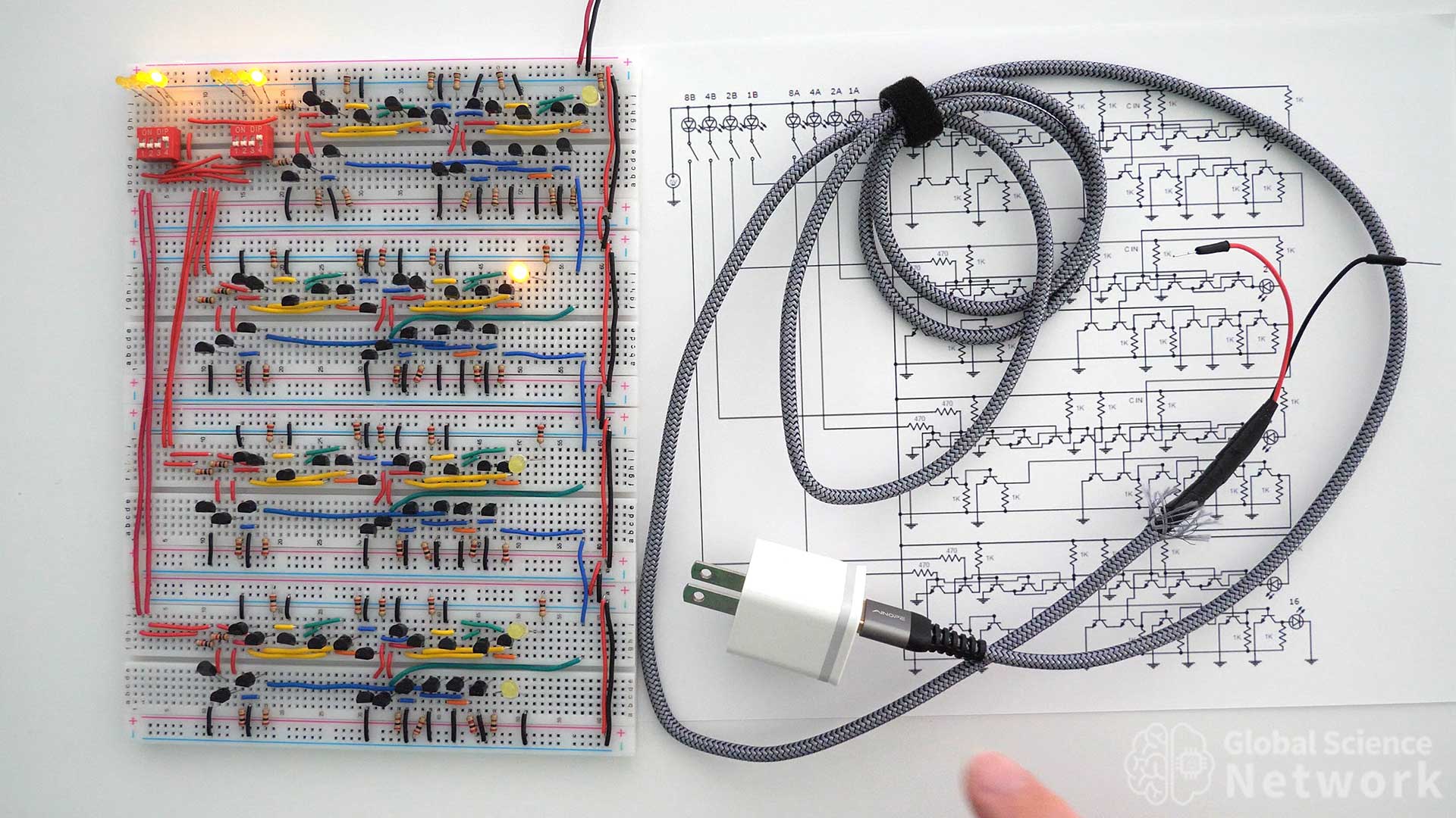
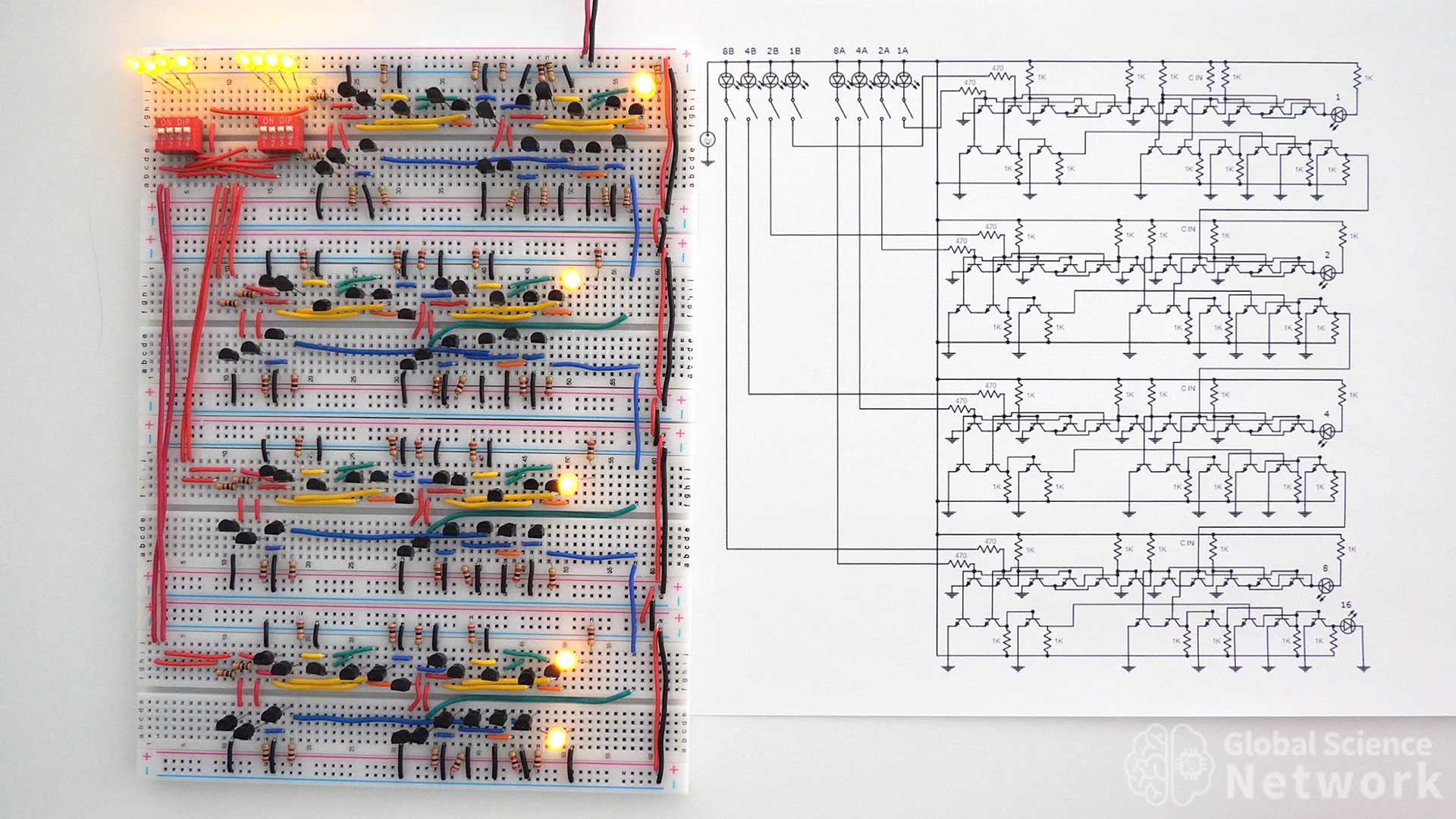
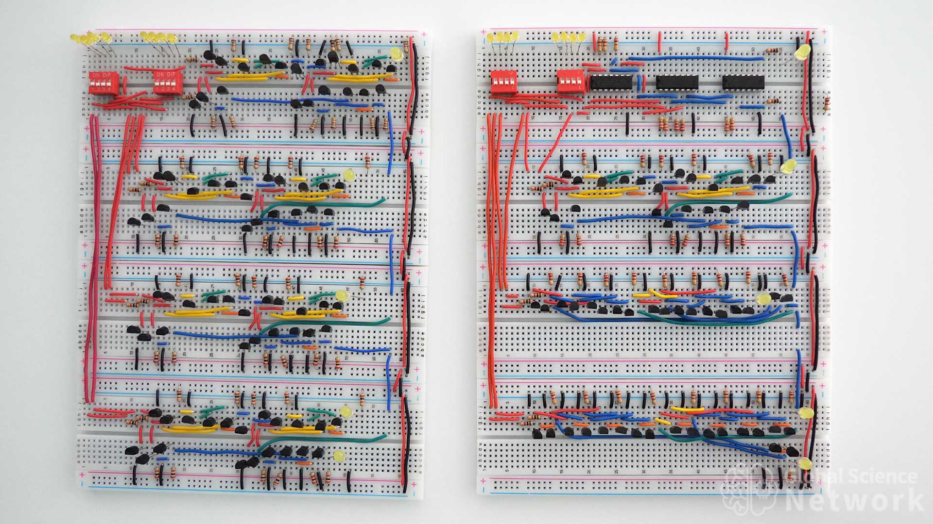
The four-bit calculator above is built by wiring four full adders together. Each full adder is implemented in a different way. The first two full adders use the same logic gate design. However, the top full adder uses integrated circuits while the second full adder uses individual transistors. The third full adder uses 9 NAND gates that are built with individual transistors. Finally, the fourth full adder is built with 9 NOR gates that are built with individual transistors.
In the video, I explain how to build this second 4-bit calculator. I also do a demonstration of the calculator working by adding several numbers.
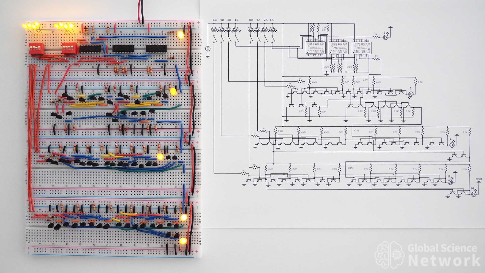
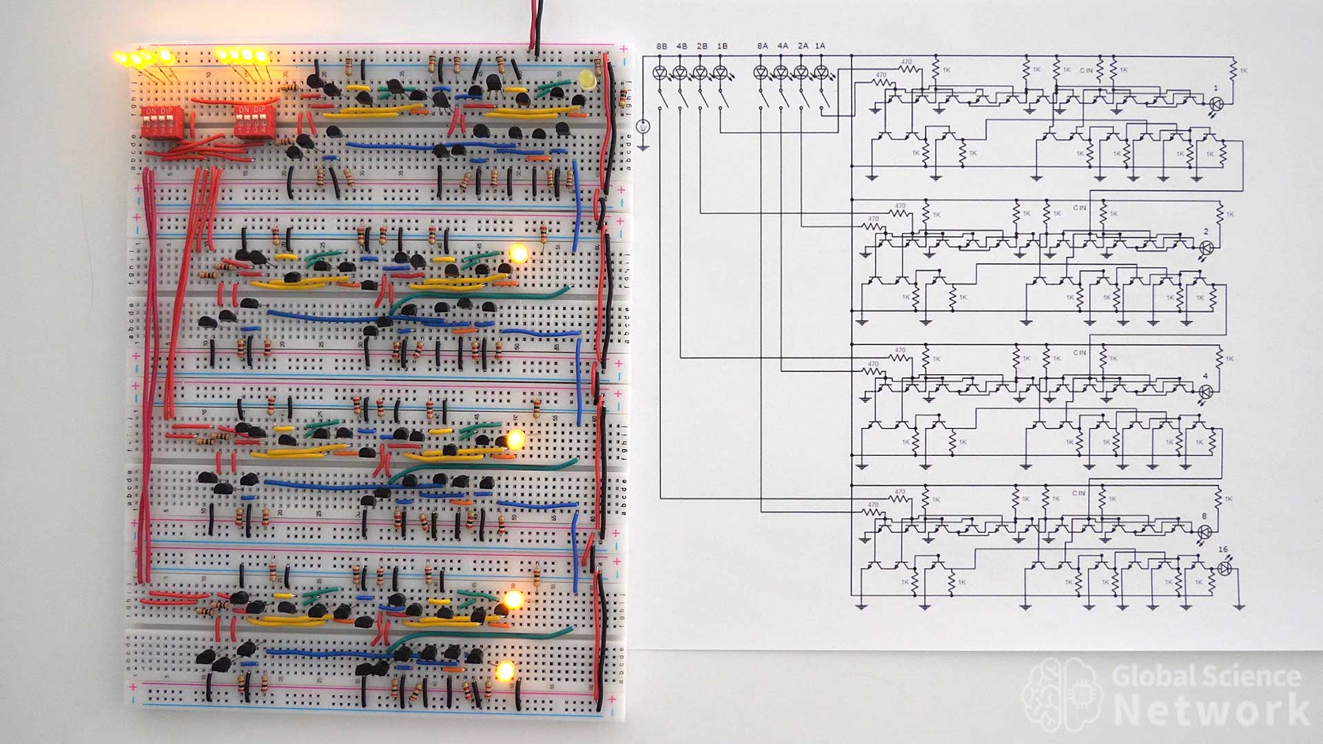
The 4-bit calculator above is made with many different types of logic gates and components. One of the great things about digital logic is there are many ways to build a circuit that will provide the same output values. The circuit is placed next to the circuit diagram to help if you plan to build this calculator as a project. Right now the circuit has the first four inputs on, the second four inputs on, and the first full adder has the carry-in on. This makes the addition 1111 + 1111 + 1 which is 31. The output is 11111 which is 31 in binary which is what the output of the calculator provided.
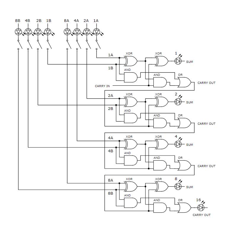
Logic Gate Level Circut Diagram
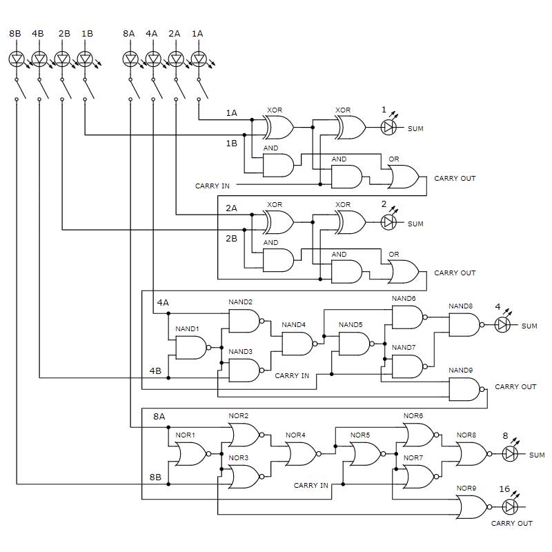
The logic gate-level circuit diagram for the 4-bit calculator is provided above. This makes it clear which types of logic gates are to be used. However, it does not provide any insight into how each logic gate should be built. The top two full adders have the same logic gate design. Integrated circuits are used for the logic gates in the first full adder while individual BJT transistors are used to build the logic gates in the second full adder. The third full adder is made with NAND gates and the fourth full adder is made with NOR gates. Each NAND and NOR gate can be built with two transistors.
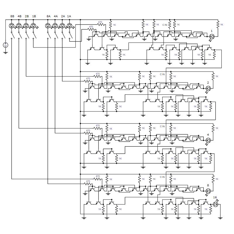
Component Level Circut Diagram
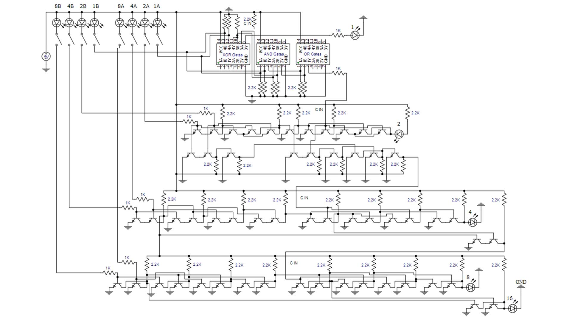
The circuit diagram above provides a detailed depiction of where every connection should be made to build the 4-bit calculator. Each full adder is built differently but the input and outputs are equal. This is an interesting way to build a 4-bit calculator cause it also demonstrates how to build six types of logic gates and shows how to implement integrated circuits. It takes around 20 hours of work to build a 4-bit calculator using individual transistors. This is because it is time-consuming to place all the components and cut the wires to the correct size. If you do build one of these calculators it is a useful way to teach others how logic gates work and how the ALU in a computer functions.
Now that you understand how to build a 4-bit calculator. Check out the video above where I build a 4-bit computer on breadboards. The ALU merged the two calculators above and added in XOR gates to allow subtraction using the 2’s complement method.

Cody started the Global Science Network with the idea people should be focusing more time, energy, and resources on useful projects. He has a bachelor’s degree in aerospace engineering and a master’s degree in mechanical engineering. Cody has worked for the US federal government, a university, a large corporation, small businesses, and for himself. He has done human brain computer interface research and is currently working towards creating non-biological human consciousness.