Breadboards are used to build and test electrical circuits. These are used by hobbyists and professional electrical engineers. Using a breadboard allows for electrical connections to be made without using solder which is why they are also called solderless breadboards. Not having to make a permanent connection with solder makes it so the placement of wires and discrete components such as resistors, LEDs, and transistors can be easily changed.
A breadboard is typically used in the prototyping stage of a circuit design. This makes it so that mistakes can be made without having to build an entirely new printed circuit board (PCB). Different designs can be tested quickly with almost instant results. Sometimes it is easier to design circuits in a circuit simulator. However, at some point in the circuit design, it should be tested with actual components to verify it works as expected. Once a final design is made on a breadboard it can then be made on a PCB which makes the circuit smaller, and easier to mass produce.
Buy from Amazon
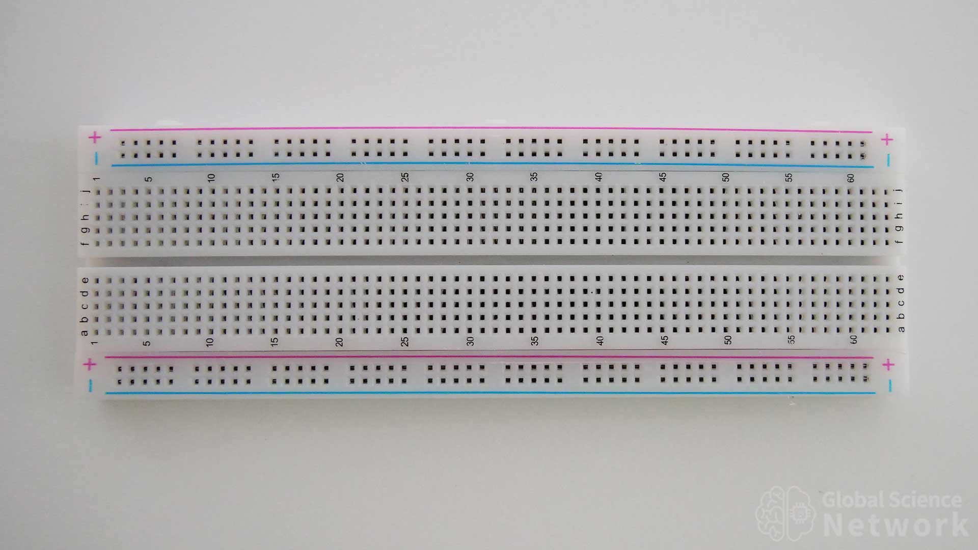
There are several different size breadboards but each one is built in a similar way. Power is supplied to the power rails which run along the outside of the breadboard. The power rails are horizontal rows. On the inside, there is a grid of holes where the rows are labeled a-j and the columns are numbered 1-60. The holes in the power rail rows are electrically connected but the rows on the inside are not electrically connected. Vertical columns are electrically connected between rows a-e and rows f-j.
The power rails are labeled + and – for where the positive and negative terminals of the power supply should be connected. Multiple breadboards can be connected together by sliding the tabs of one breadboard into the grooves of another. A breadboard can also be secured to a flat surface as the bottom has a sticky layer that can be exposed by removing the paper backing.
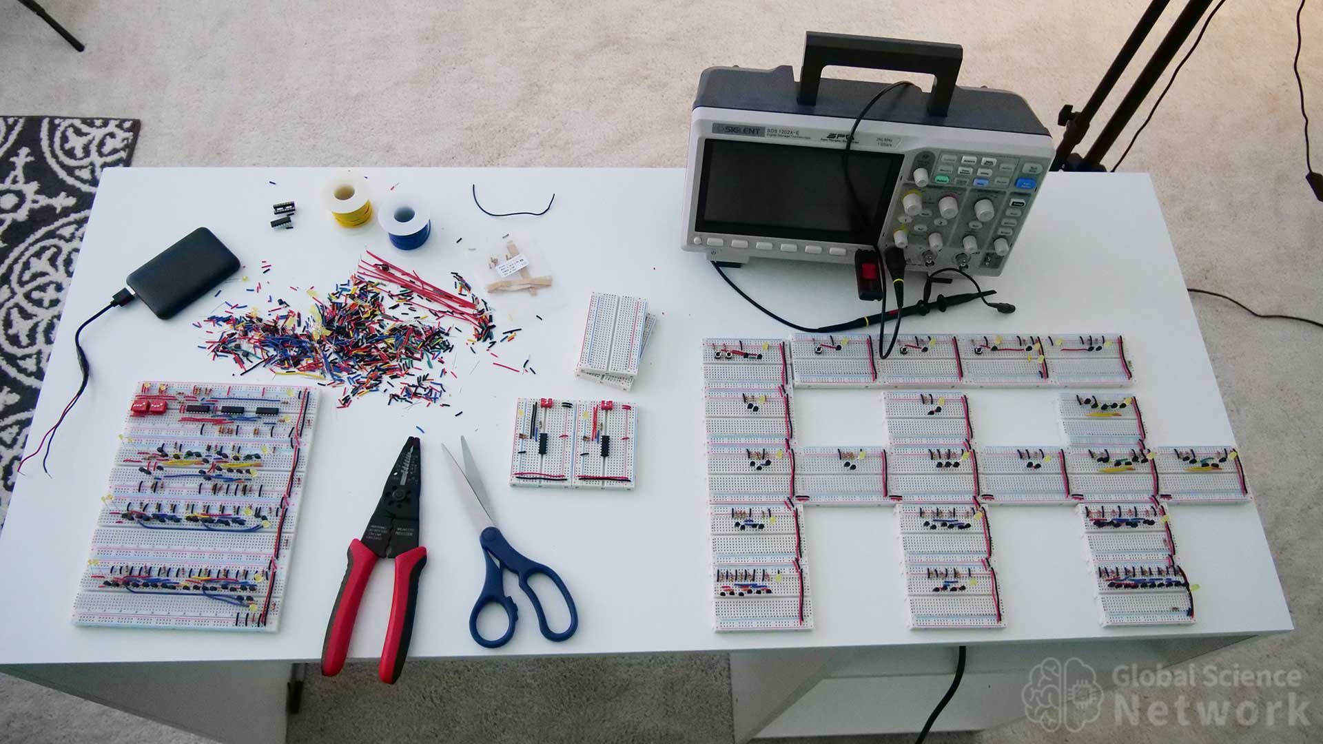
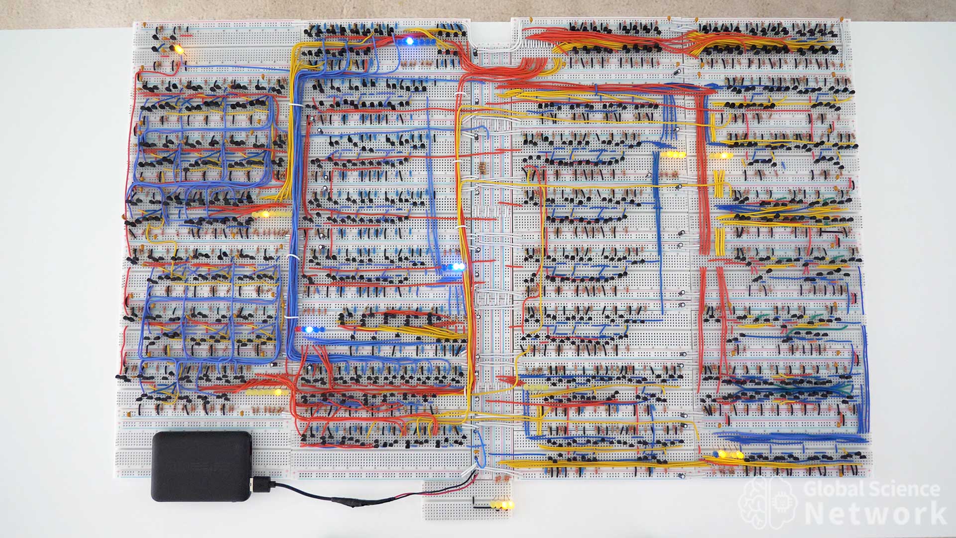
In the photo above I am working on multiple breadboard projects involving digital logic gates. An oscilloscope is used to measure voltages within the circuits. On the desk, there is a large number of cut wire scraps as each wire is custom cut to length. Both full-size and half-size breadboards are being used.
Breadboard Components
Wire
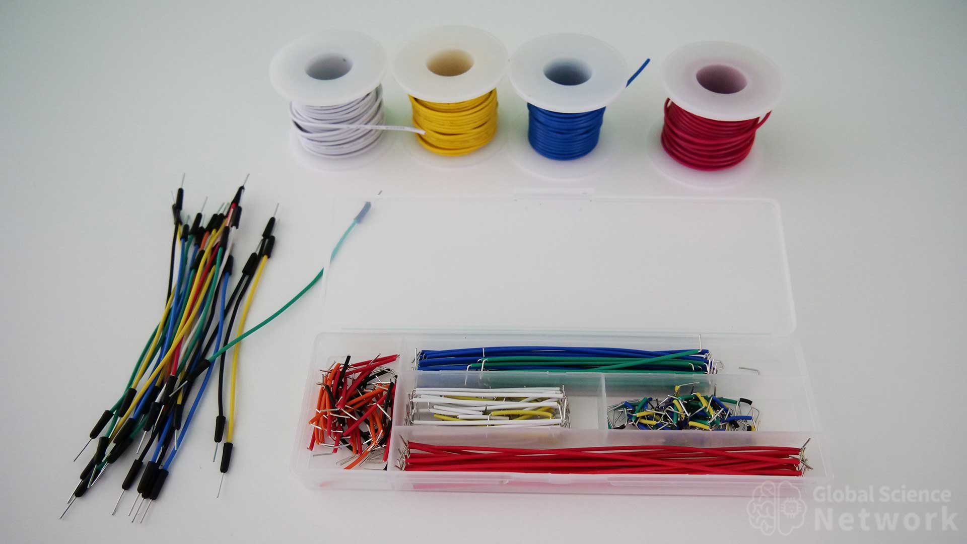
There are three different types of wires used for breadboarding. These are jumper wires, spools for wire, and pre-cut wire. Each will be discussed in detail below.
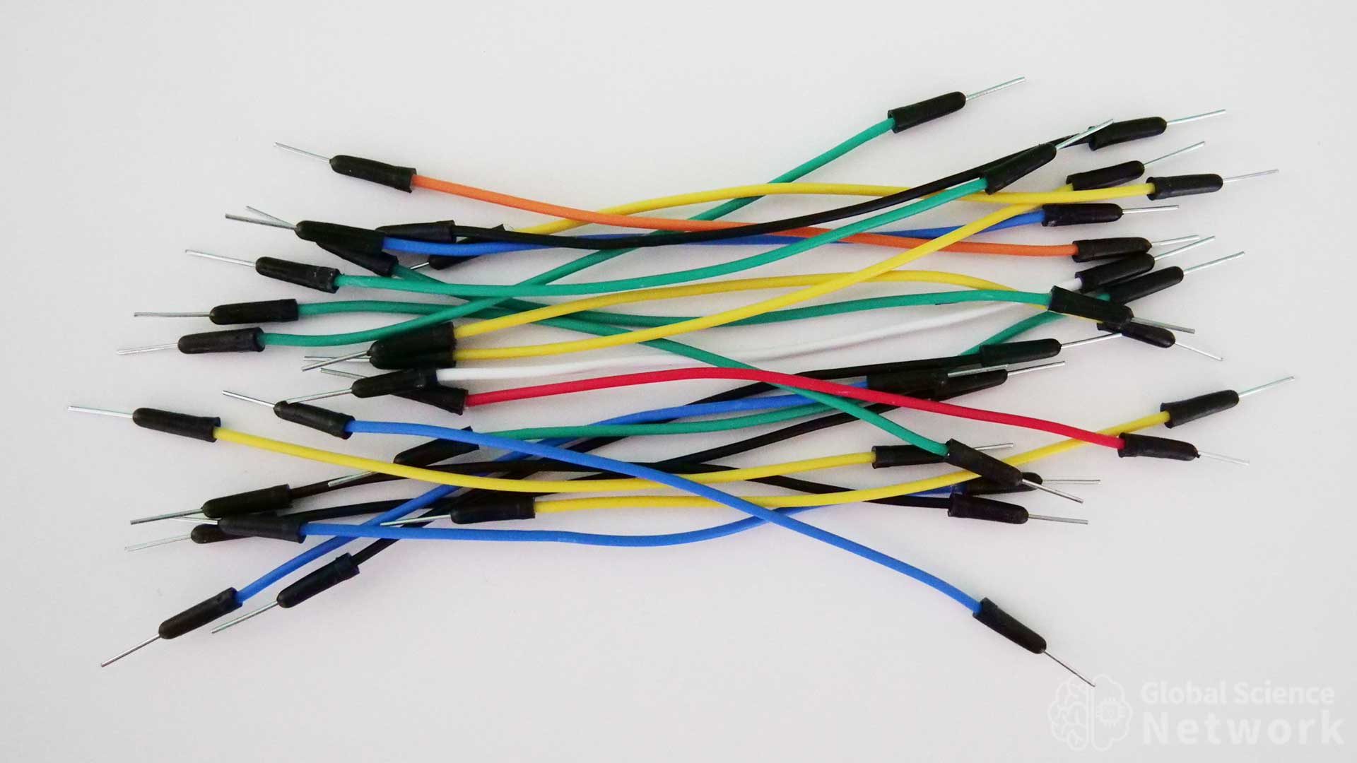
Flexible jumper wires are the quickest and easiest way to make a wire connection on a breadboard. These are made with multistrand wire with a PVC coating. Multistrand cable is flexible but does not fit well into breadboard holes. For this reason, there are metal pins on the end that fit properly into the holes of the breadboard. The disadvantage of using jumper wires is the extra length of wire makes it less clear where each wire is going to and from. This is especially true when lots of wired connections are made. Jumper cables are great for quick testing but are not to build circuits to take pictures of and show circuit designs to others.
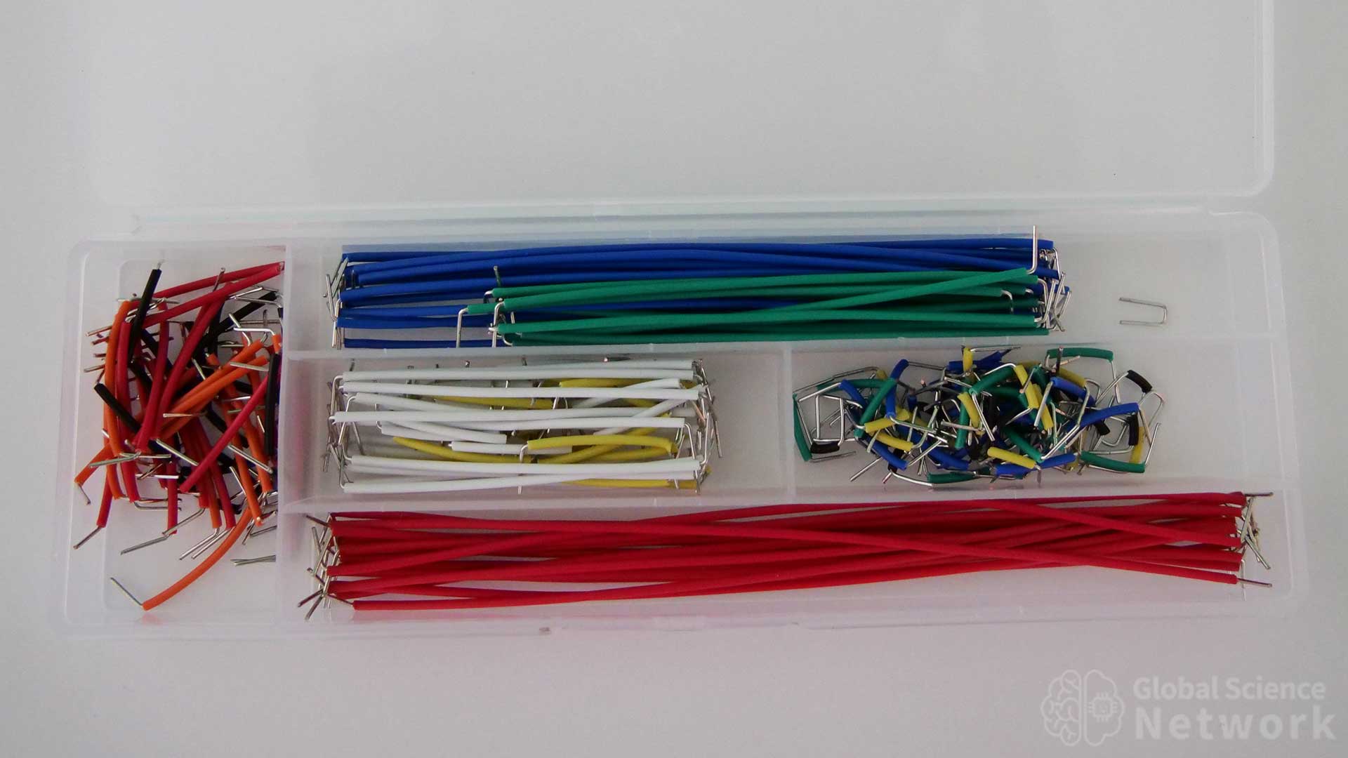
Precut wires can be nice because the wires are cut and bent to specific lengths. This does help speed up the process when breadboarding. The problem is that the wires are color coated based on length. Often times when building circuits it is nice to color code the wires based on the connection type. For example black going to the ground, red going to the positive rail, blue wires sending data, etc. I do use precut wire when the wire I need is shorter than the precut wire. This way I can cut it down and still use the color I want. It saves some time as one end is stripped and bent already.

Buy from Amazon
The best wire to use for breadboards comes on spools. It is a 22 gauge solid core wire. Each spool has over 25 feet of wire. Common wire colors are red, black, yellow, blue, white, and green. The disadvantage of the wire spools is that each wire needs to be cut to length and stripped on both sides to expose the wire. When this is done properly it makes for a very nice-looking circuit where it is easy to see where the wires are going to and from. So it is often worth the extra time. Each wire should be cut so that it lays flat and the stripped ends fit securely in the holes.
Resistors
Buy from Amazon
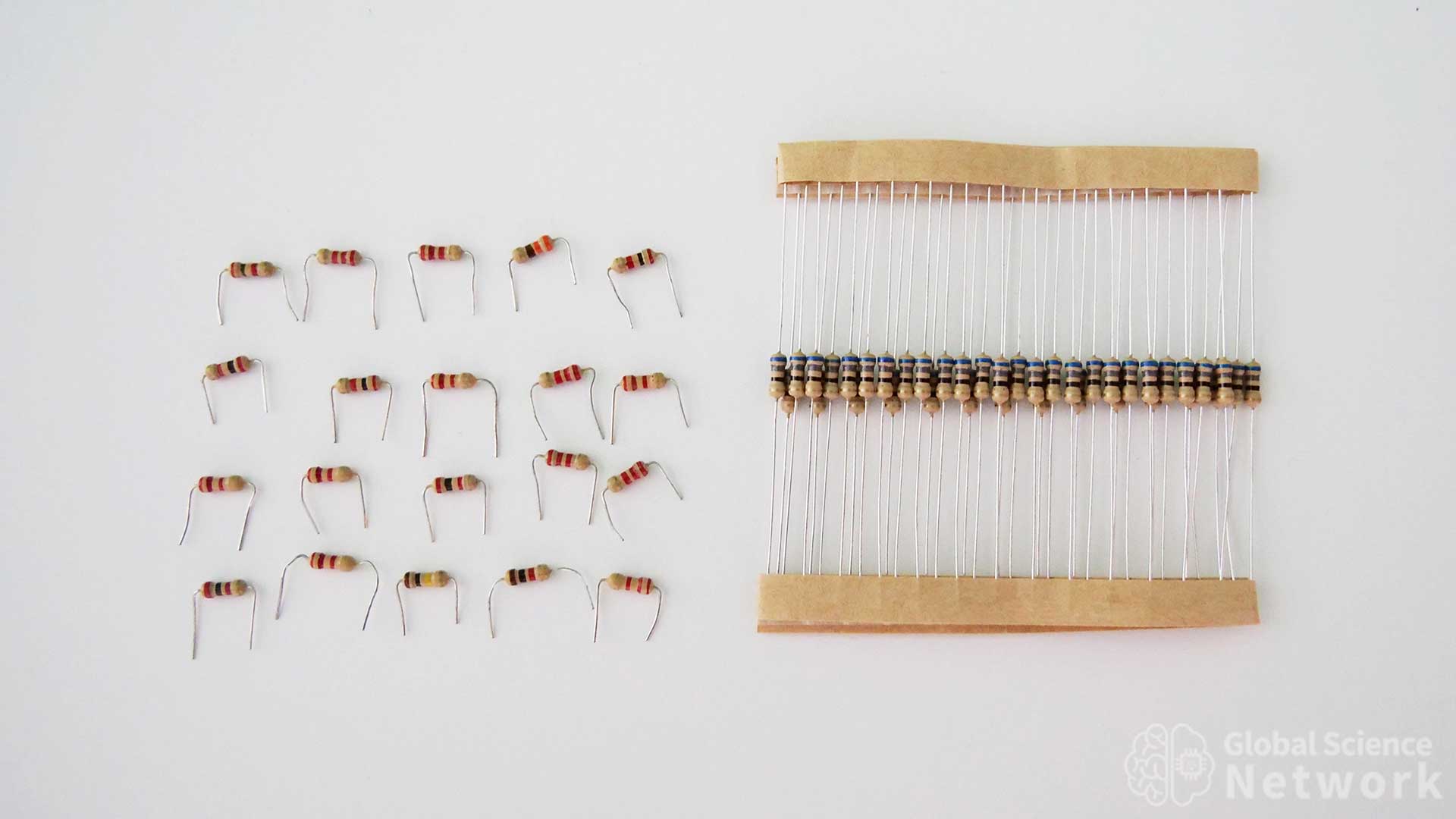
Resistors are one of the most common components used when breadboarding. Each resistor is marked with color-coated bands to display its value. Common resistor values used for breadboards range from 1 ohm to 1 mega ohm which is 1 million ohms. Often times the exact value of the resistor is not needed so one with a slightly higher value should be used. For example, if your calculations show you need a 945-ohm resistor, using a 1K resistor will work in most cases.
Resistors come with long wires on each end that need to be cut and bent to fit properly in the breadboard. The full length can be used but in most cases, this will make the resistor sit high above the breadboard. Having resistors lie flat makes the breadboard look more organized and is easier to see where connections are being made.
LEDs
Buy from Amazon
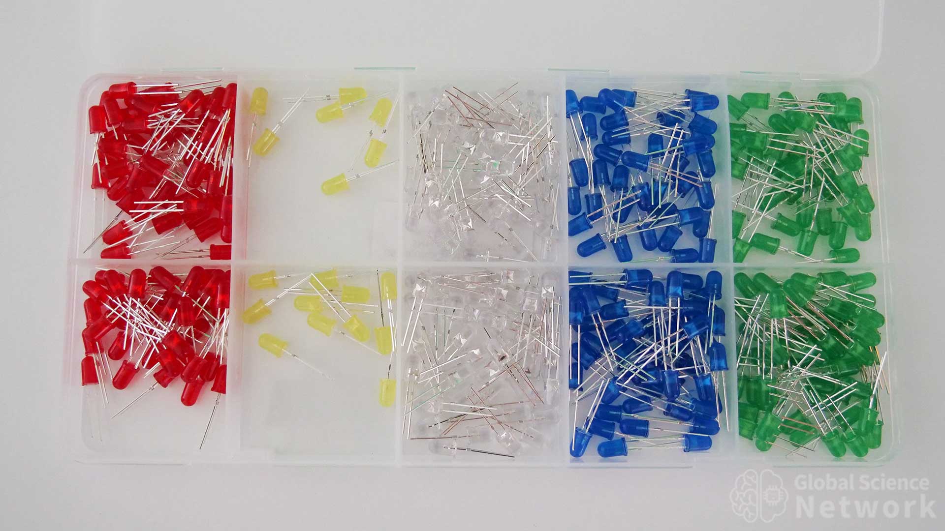
LEDs are often used in breadboards to show that the power is on. Using an oscilloscope or multimeter can provide the exact power value. However, often times it is advantageous to just see that power is on. Also, the brightness of the LED gives insight into how much current is being applied across the LED. When using LEDs it is important to have a current-limiting resistor or the LED can be damaged.
Most LEDs have a voltage drop ranging from 1.8 volts to 3.2 volts. This is different from standard diodes which have a voltage drop of around .6 volts. The common input voltage for breadboards ranges from 3 volts to 9 volts. If the resistor is larger than 350 ohms it should limit the current to less than 20 milliamps. The max current rating for LEDs is typically 20-25 milliamps. Common colors for LEDs are red, yellow, white, blue, and green.
Transistors
Buy from Amazon
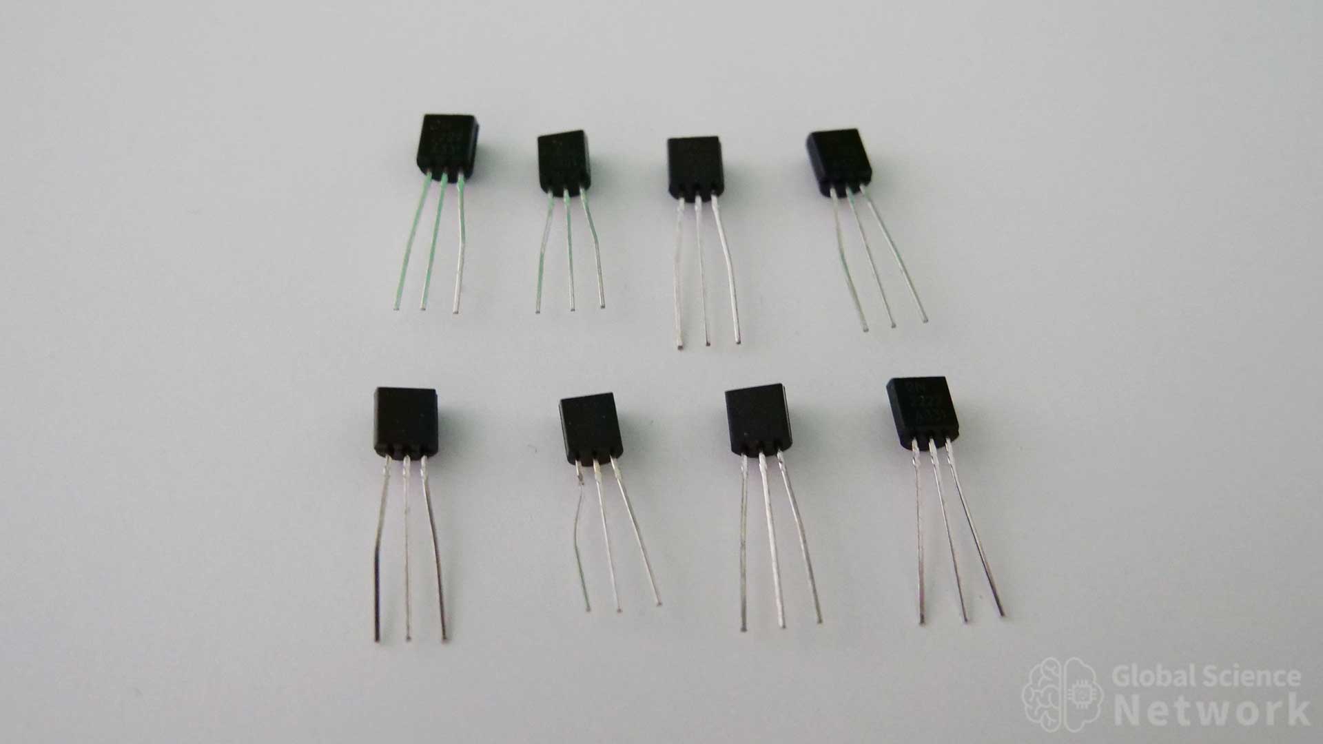
BJT transistors have three pins that are designed to work with breadboards. The three pins are the emitter, base, and collector. Which pin is which will vary depending on if it is an NPN or PNP transistor. The most common transistor used with breadboards is the 2N2222 NPN transistor. This is an amplifying transistor and also works as a switching transistor. I have used these to build digital logic gates. Like LEDs, transistors should also have a current-limiting resistor to prevent damage.
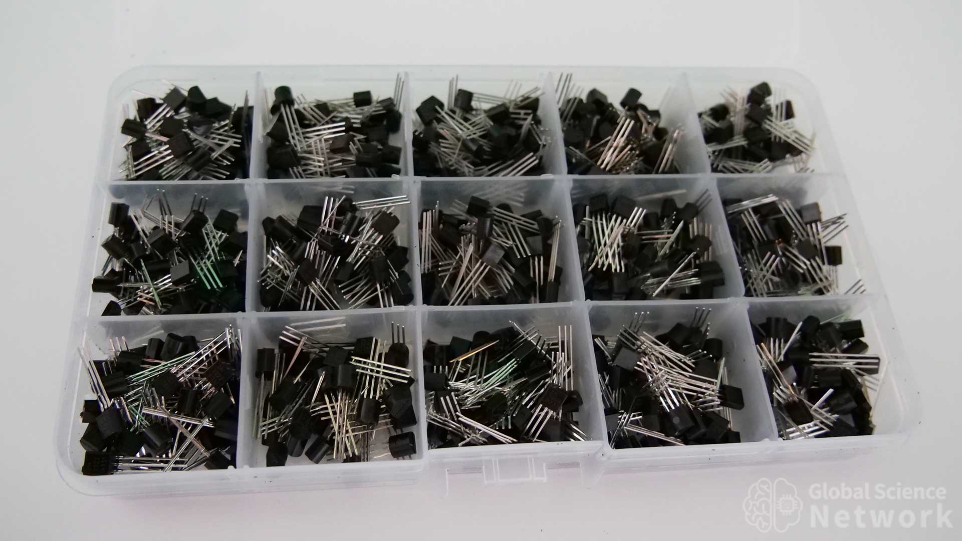
Transistors often come in large sets where the are many types of NPN and PNP transistors. The most common NPN transistors are the 2N2222 and the 2N3904. For PNP transistors the most common are the 2N2907 which is equivalent to the 2N222 and the 2N3906 which is equivalent to the 2N3904. Each transistor does have different specifications so using the proper model number is important.
Capacitors

Buy from Amazon
The three types of capacitors used with breadboards are ceramic capacitors, aluminum electrolytic capacitors, and metalized polypropylene capacitors which are also called film capacitors. In the photo above is a set of ceramic capacitors. These have a capacitive range from 0.1 µF to 10 µF. Ceramic capacitors are non-polarized meaning the orientation of the capacitor is not important. Electrolytic capacitors are polarized meaning one terminal must be connected to the positive voltage and the other side must be connected to the ground side. If this is done in reverse the capacitor will quickly heat up and break, often resulting in a popping noise and the smell of melting capacitor material. Most film capacitors are not polarized. Breadboard capacitors can range in size from 10 pF to 10,000 µF.
Integrated Circuits
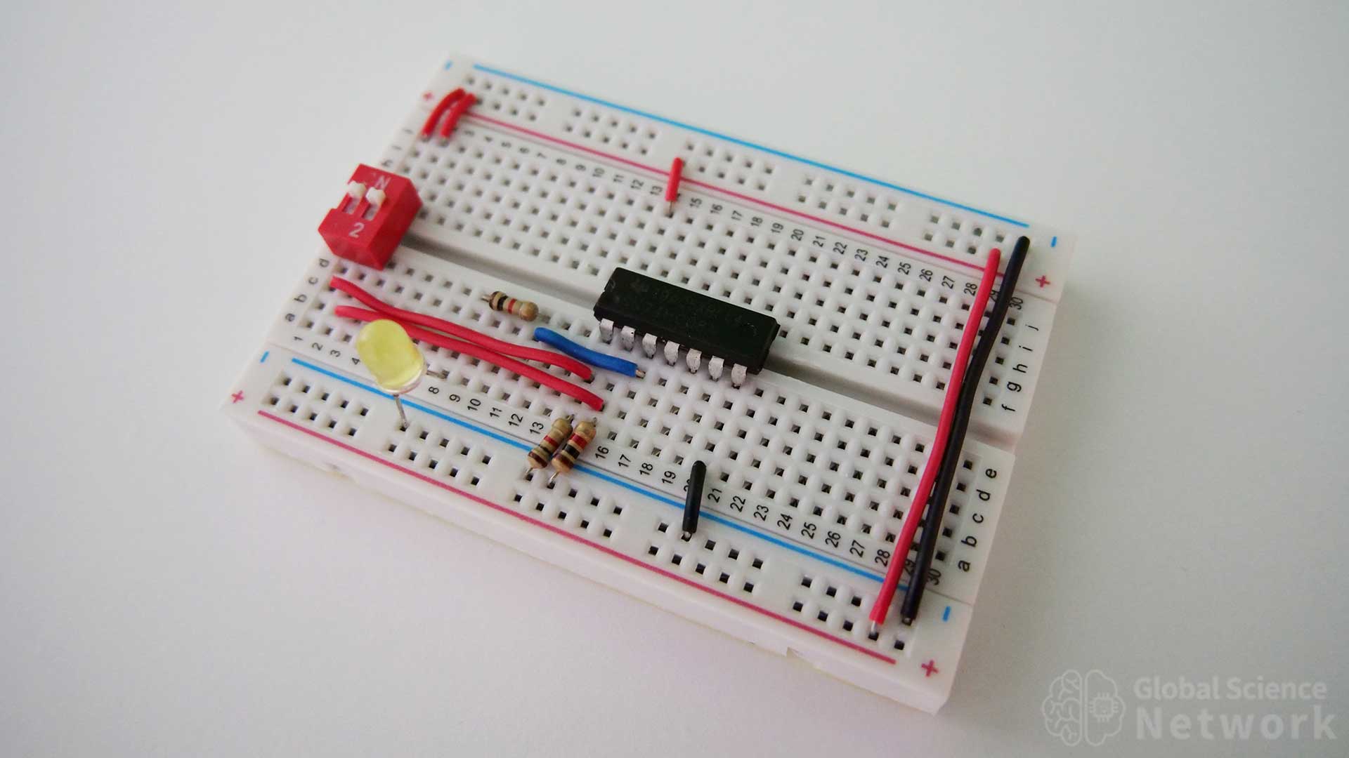
Breadboards are also designed to work with integrated circuits. An entire microprocessor can be placed on an integrated circuit so ICs drastically increase the potential of what can be done on a breadboard. Common integrated circuits to use on breadboards include logic gates, 555 timers, op-amps, shift registers, EPROM, FPGAs, gyroscopes, and microprocessors.
BreadBoard Tools
Wire Stripper

Buy from Amazon
Wire strippers are needed to cut wires and remove the wire insulation on the end of the wire. Breadboard wires are 22 gauge so the stripper needs to have a slot to strip 22 gauge wire insulation. The wire stripper above can cut and strip wire from 10 gauge to 22 gauge. It also has a crimper to make crimp connections. When cutting breadboard wire to exact lengths some type of cutter and wire stripper is needed.
Wire Cutter

Buy from Amazon
Scissors or a wire cutter make cutting wire much easier. The wire stripper tool does have a cutter but only on the back of the jaws. Having a tool with a cutter on the front jaws makes it easier to mark where the wire needs to be cut. Resistor wire is very thin and is easy to cut with scissors. I often cut multiple resistor wires down to the proper size with just one cut on each side. A small wire cutter is probably best but scissors do work if that is what is available.
Breadboard Power Supply
A breadboard can be powered by a variety of power supplies. Batteries used to be the most common way to power a breadboard. Two 1.5-volt batteries in series make a 3-volt power source. Three 1.5-volt batteries in series can be used to supply 4.5 volts. One 9-volt battery works with connector clips and power wires. There are also breadboard power supply modules that can provide 3.3V or 5 volts. The module can receive input power through a 2.1 mm jack plug or USB cable. The disadvantage of the breadboard module is that it takes up space on the breadboard. Power can also be sent from an Arduino, Raspberry Pi, or microcontroller to the breadboard.
USB Battery Pack
Buy from Amazon
In the photo above I am providing power to a 4-bit calculator that is built on breadboards using a 5-volt battery pack. I modified a USB power cable so that it could go into the positive and negative terminals of the breadboard. This was done by splicing solid core 22 gauge wire from the stranded cable that was in the original power cable. The only downside to using this battery pack is it does have an auto shut-off feature if the output current is too low. It stops supply power after about 30 seconds when this is the case. Pushing the button on the battery pack will allow the current to flow for another 30 seconds. This is ok when testing circuits because you typically know within 30 seconds if the circuit is working properly. For larger circuits, it will not shut off as the current used is high enough to not shut the power off.
Cell Phone Charger and USB Cable
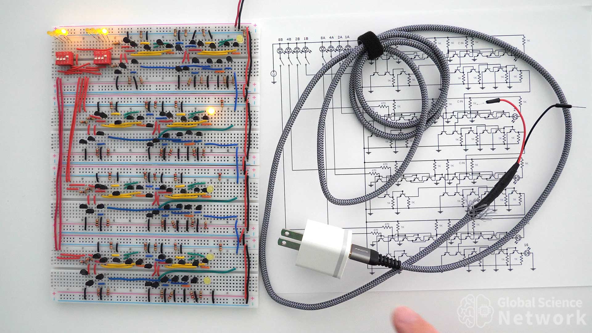
Using a 5-volt cell phone charger is becoming a popular way to power a breadboard. Most cell phone chargers and USB ports from computers provide a 5-volt power source. In the photo above I modified a 6-foot USB cable to have breadboard jumper cable ends. Now, most USB power supplies will work to power the breadboard at 5 volts.
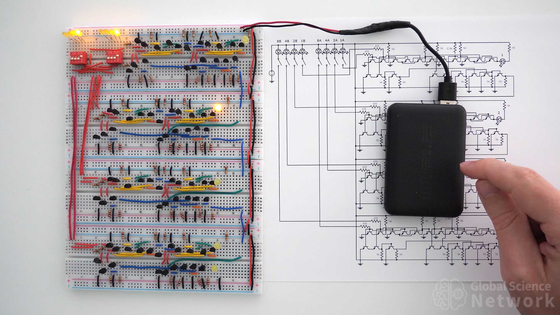
External Circuit With USB Power Supply
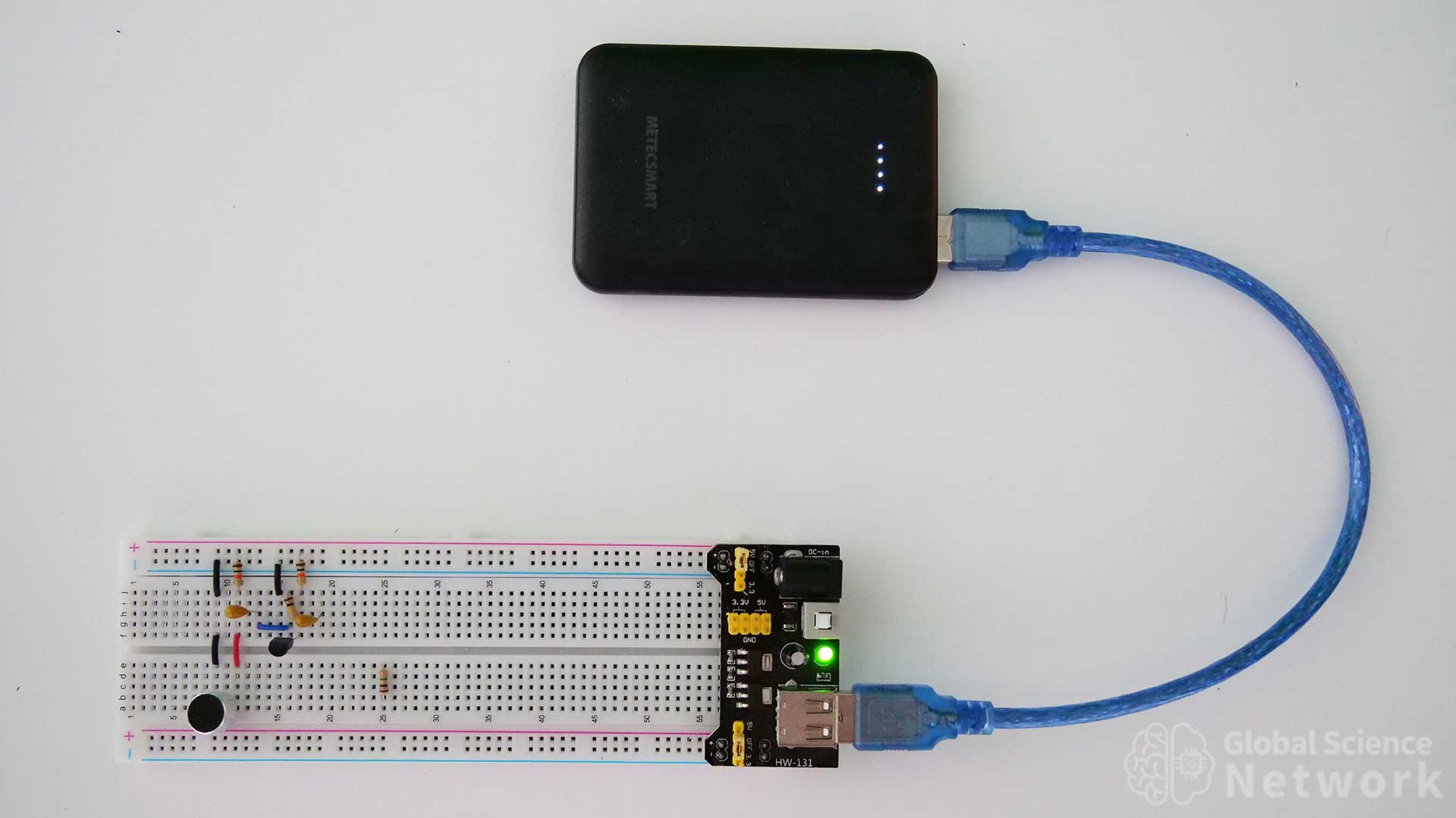
The photo above shows how to connect power to a breadboard power supply module using a USB cable. A 5-volt battery pack is supplying the power. The module receives power from the USB cable. Jumpers above each power rail can be moved so that 5 volts, zero volts, or 3.3 volts is supplied to the power rail. The top and bottom power rails can be set to different values. In the photo, the top power rail is set to 5 volts and the bottom power rail is set to zero volts. A green LED on the board indicated the power is being supplied to the board. There is a button that turns the power off to the board and the LED will shut off when power is not being supplied to the breadboard.
Power Supply Module
Buy from Amazon
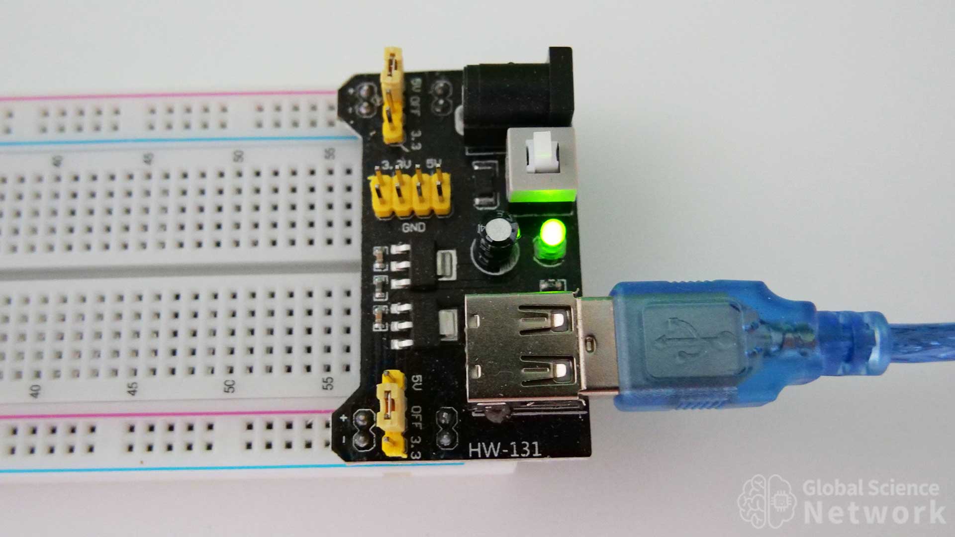
The close-up view of the power supply modules shows all the features of the board. Input power can come from the jack plug or USB cable. Power going into the power jack needs to be between 6.5 and 9 volts. Power coming from the USB should be around 5 volts. The module is connected to the breadboard with 8 pins. Four pins on each side go into the power rails. This is an ok option to power a breadboard. I personally prefer when power is supplied over two wires. It makes it so there is more room on the breadboard and makes the breadboard less cluttered. When making demonstration videos it is also nice not having people wonder what is going on with the power supply. It is simpler to just show a red wire and a black wire going into the positive and negative slots in the breadboard.
Buy from Amazon
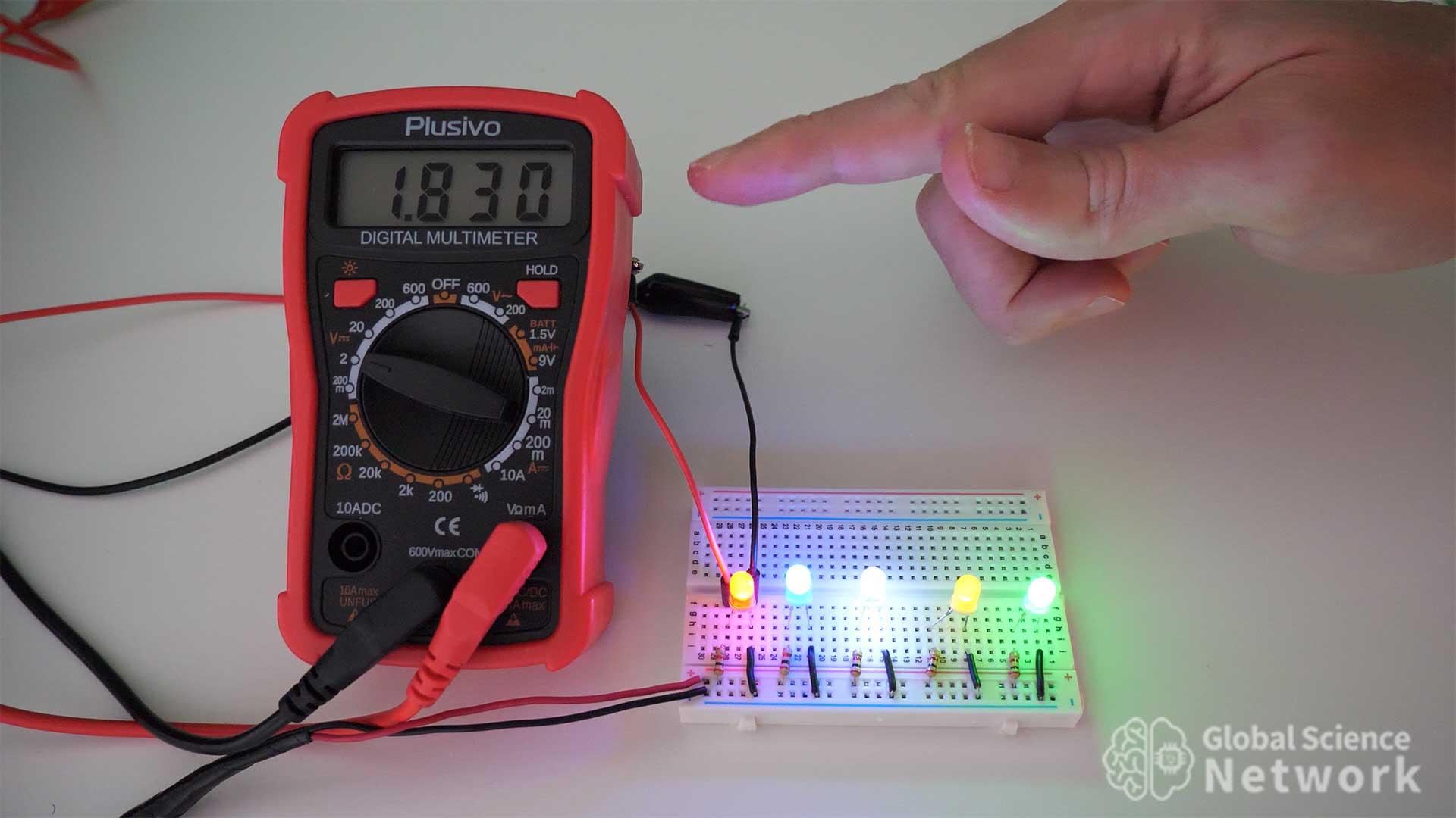
A multimeter provides a way of measuring the current in the circuit. It is also a way to measure the voltage levels within the circuit. I do use this multimeter to determine the current. For voltage levels though, I prefer to see the output on the oscilloscope as this provides transient information as well.

Buy from Amazon
Having a digital oscilloscope is really handy when working with circuits. It is often difficult to know what is going on within the circuit without looking at the voltage values at different locations within the circuit. The oscilloscope not only shows the voltage values but shows the values over time so you can see transient conditions within the circuit.
Cody started the Global Science Network with the idea people should be focusing more time, energy, and resources on useful projects. He has a bachelor’s degree in aerospace engineering and a master’s degree in mechanical engineering. Cody has worked for the US federal government, a university, a large corporation, small businesses, and for himself. He has done human brain computer interface research and is currently working towards creating non-biological human consciousness.
4-Bit Calculator Built Using Digital Logic Gates
Building a 4-bit calculator using individual transistors helps demonstrate how computers add numbers. This can be thought of as a simple arithmetic logic unit (ALU) for a computer. In this case, the calculator is a stand-alone device that can add two 4-bit inputs together. In binary, the highest 4-bit input is 15 which is 1111 in binary. There is also a carry-in slot in the first full adder so the calculator can add 15+15+1 for a max value of 31 which is 11111 in binary.
The photo above shows the 4-bit calculator I built on four breadboards. Two 4-slot dip switches control whether the inputs are on or off. When an input is on the dip switch will be in the up position and the LED above the dip switch will be on. When an input is off the dip switch will be in the down position and the LED above the dip switch will be off. The output is represented by the 5 LED lights on the right-hand side of the breadboard. The position of the LED determines its value. When the top LED is on it represents 1, the second LED represents 2, the third LED represents 4, the fourth LED represents 8, and the fifth LED represents 16. If all 5 LEDs are on it is 11111 in binary which is 15 in the base 10 number system.
4-Bit Calculators
In this article, I am going to show two different ways to build a 4-bit calculator. The first is going to use 4 full adders that are all built the same way. Next, I am going to show how to use 4 full adders which are all built differently to build a second 4-bit calculator. This will help demonstrate that there are multiple ways to design digital logic gate circuits that perform the same operation. Building a 4-bit calculator would be a fun circuit science project for someone looking to further their understanding of digital logic gates. I plan to take the first 4-bit calculator and used it as an ALU for a 4-bit computer that is built with individual transistors.
The video above shows how to build the first 4-bit calculator using individual transistors. It also explains the binary number system to describe how the calculator adds in base 2. At the end of the video the calculator is tested by varying the two 4-bit inputs and it works as expected. The calculator is powered by a 5-volt battery pack that is typically used to charge cell phones.
4-Bit Calculator Built with Individual Transistors
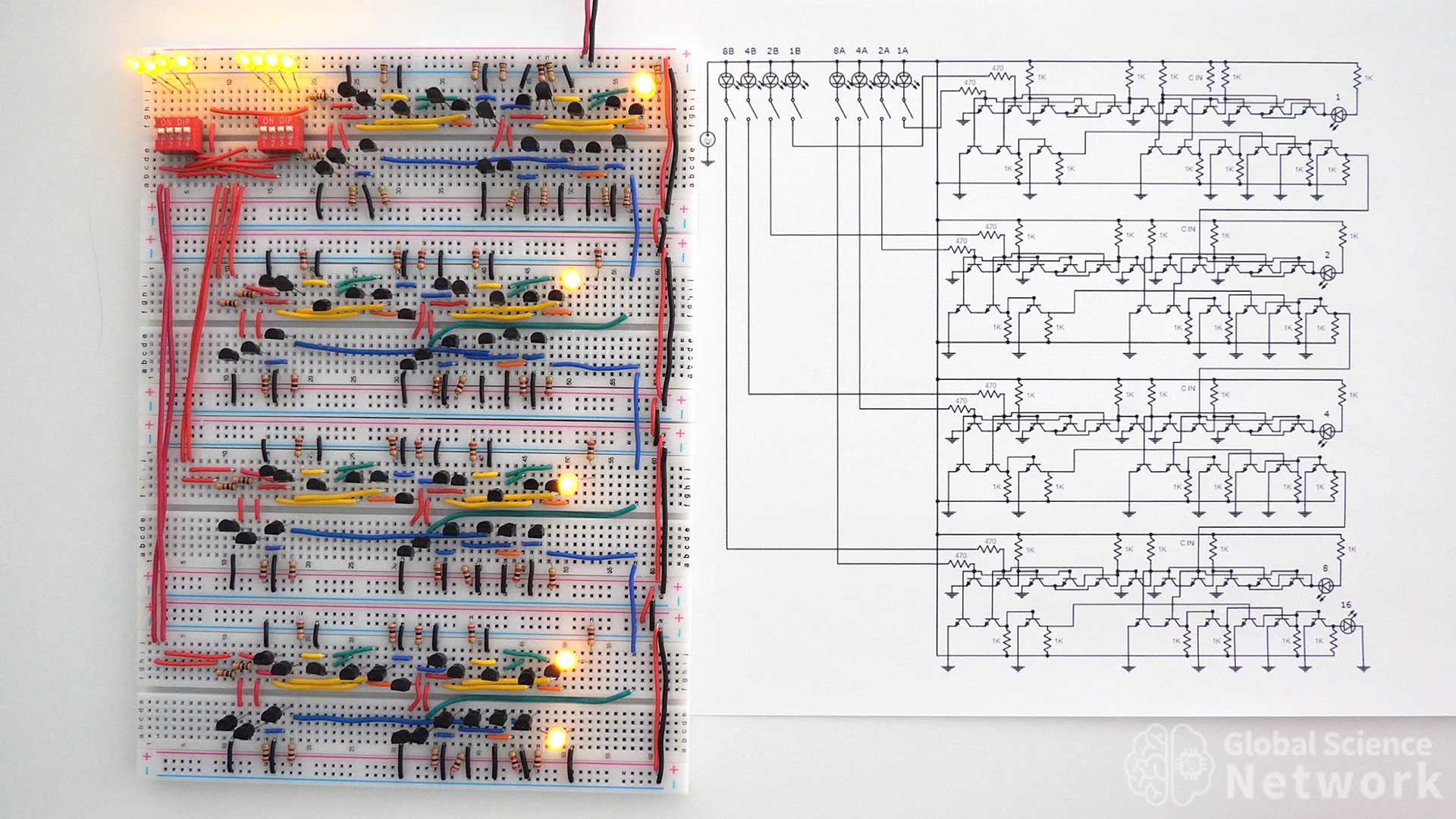
The first 4-bit calculator is shown above. There are four breadboards that are connected together. Each breadboard has one full adder. The first full adder also has dip switches to turn the inputs on or off. All of the resistor values used are 2K. On the left side of the calculator red wires run from the top positive 5-volt rail to inputs A and B of each full adder. The carry-out of full adder 1, full adder 2, and full adder 3 feed into the carry-in location in the next full adder. On the right-hand side, red and black wires connect power to each breadboard. The main power is supplied to the top breadboard from the two wires on the top right-hand side of the calculator. All of the transistors used are NPN type with a model number of 2N2222, and model number 2N3904 will also work as these have very similar properties.
In the photo the first 4 inputs are on, the second 4 inputs are on and the carry-in is off. This means that 1111 + 1111 + 0 is what is being added. The output should therefore equal 30 which is 11110 in binary. If you look at a calculator you can see that the LED lights show an output of 11110 as expected.
Logic Gate Level Circut Diagram
The logic gate-level circuit diagram is shown above. Each full adder is built with 2 XOR gates, 2 AND gates, and an OR gate. The inputs are in the top left corner of the circuit while the outputs are on the right-hand side of each full adder. Inputs are labeled based on their value for example input 4A has a value of 4 based on its position in the circuit. This diagram provides a high-level design of how the 4-bit calculator should be built. It does not however detail how each logic gate is to be built.
Component Level Circut Diagram
The component-level circuit diagram for the 4-bit calculator is shown above. This shows how each logic gate is to be wired using individual transistors. Each full adder is built the same way. So once it is understood how to build one full adder it is not difficult to wire four of them together to form the adder circuit. In each full adder, the first 6 transistors are the first XOR gate, and the next 5 transistors are the second XOR gate. The second XOR gate does not send an output so one less transistor is needed. In the bottom row of each full adder, the first three transistors are the first AND gate, the next three are the second AND gate. Finally, the last three transistors are the OR gate.
All resistor values are labeled 1K except the input resistors which are 470 ohms. The input resistors are lower because the inputs have a 1.9-volt voltage drop across the input LEDs being used to show if the input is on or off. The carry-in on the first full adder is turned on by connecting the second input of the second AND gate to the 5-volt rail. This is done by adding a resistor to the carry-in location.
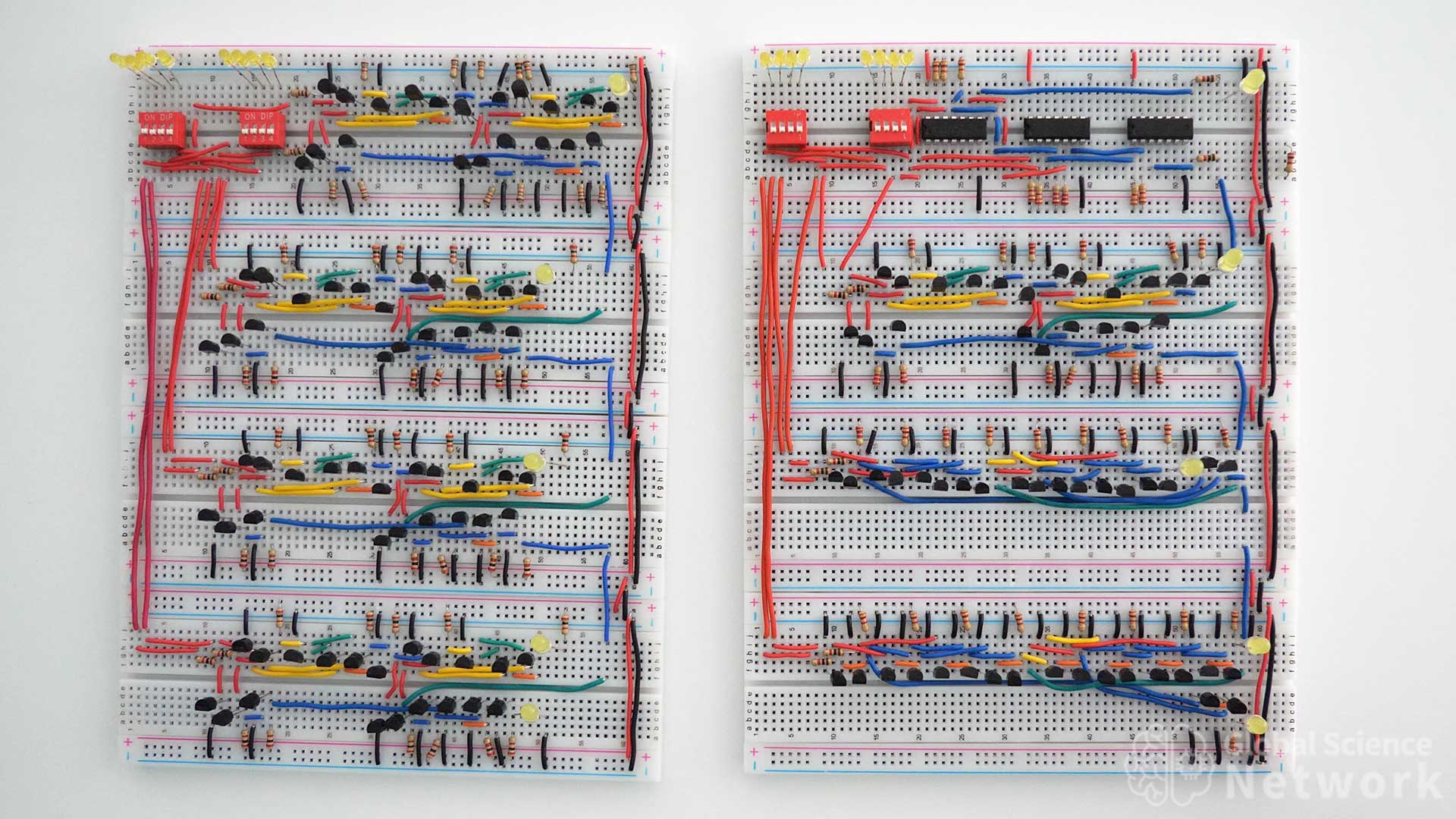
4-Bit Calculator Built with Different Types of Logic Gates
The four-bit calculator above is built by wiring four full adders together. Each full adder is implemented in a different way. The first two full adders use the same logic gate design. However, the top full adder uses integrated circuits while the second full adder uses individual transistors. The third full adder uses 9 NAND gates that are built with individual transistors. Finally, the fourth full adder is built with 9 NOR gates that are built with individual transistors.
In the video, I explain how to build this second 4-bit calculator. I also do a demonstration of the calculator working by adding several numbers.
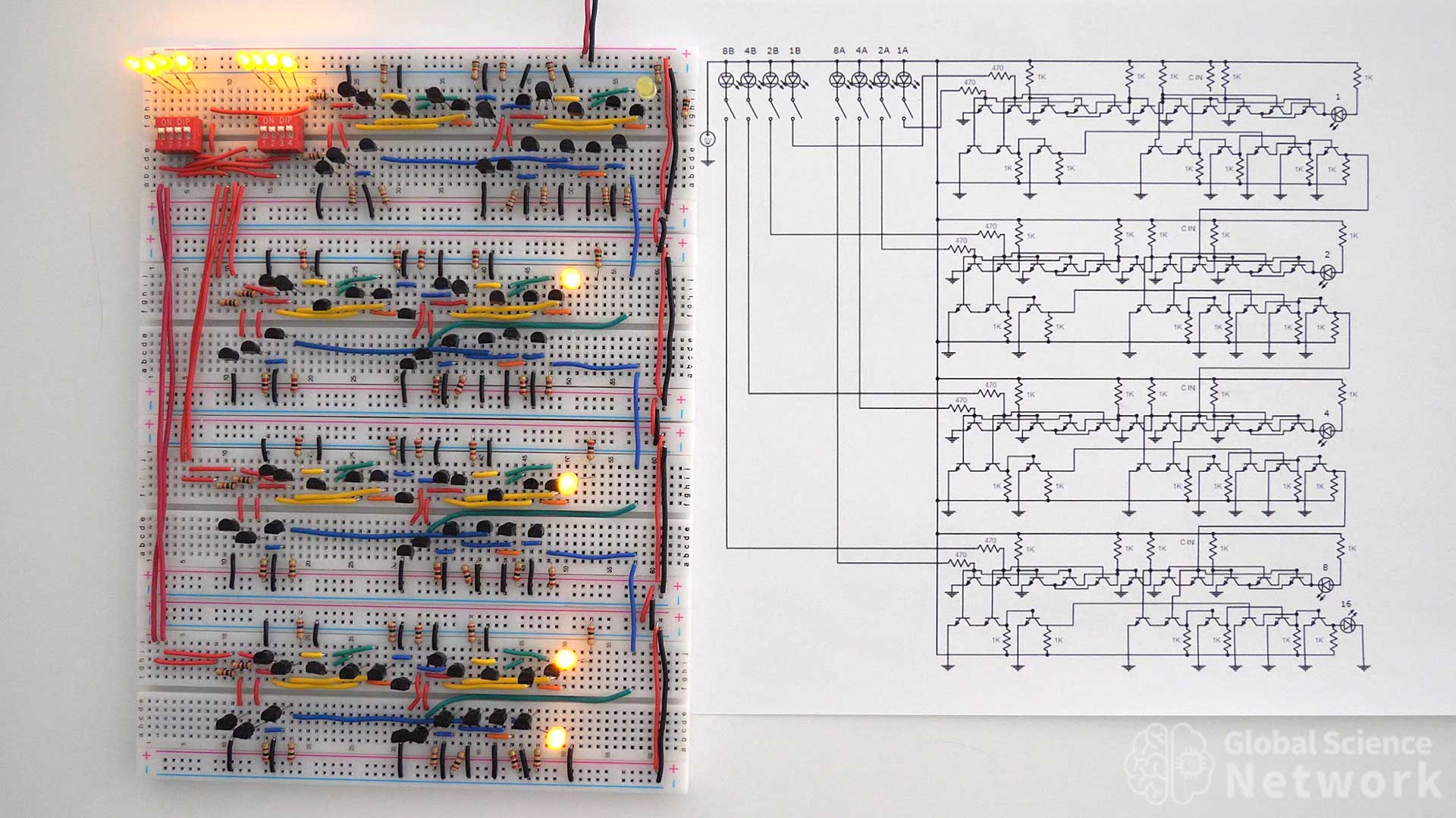
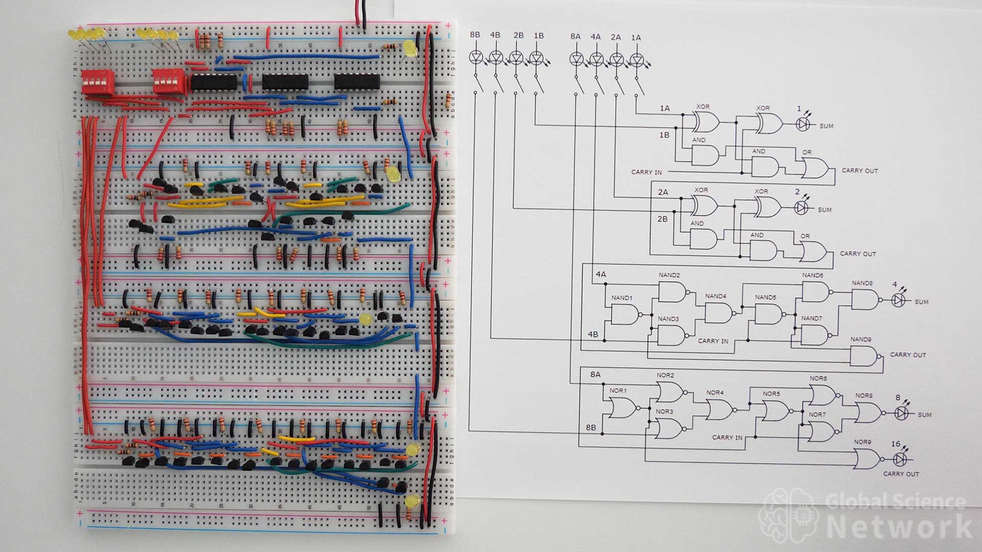
The 4-bit calculator above is made with many different types of logic gates and components. One of the great things about digital logic is there are many ways to build a circuit that will provide the same output values. The circuit is placed next to the circuit diagram to help if you plan to build this calculator as a project. Right now the circuit has the first four inputs on, the second four inputs on, and the first full adder has the carry-in on. This makes the addition 1111 + 1111 + 1 which is 31. The output is 11111 which is 31 in binary which is what the output of the calculator provided.
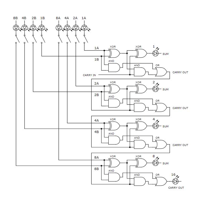
Logic Gate Level Circut Diagram
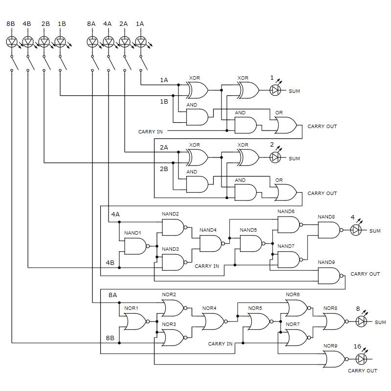
The logic gate-level circuit diagram for the 4-bit calculator is provided above. This makes it clear which types of logic gates are to be used. However, it does not provide any insight into how each logic gate should be built. The top two full adders have the same logic gate design. Integrated circuits are used for the logic gates in the first full adder while individual BJT transistors are used to build the logic gates in the second full adder. The third full adder is made with NAND gates and the fourth full adder is made with NOR gates. Each NAND and NOR gate can be built with two transistors.
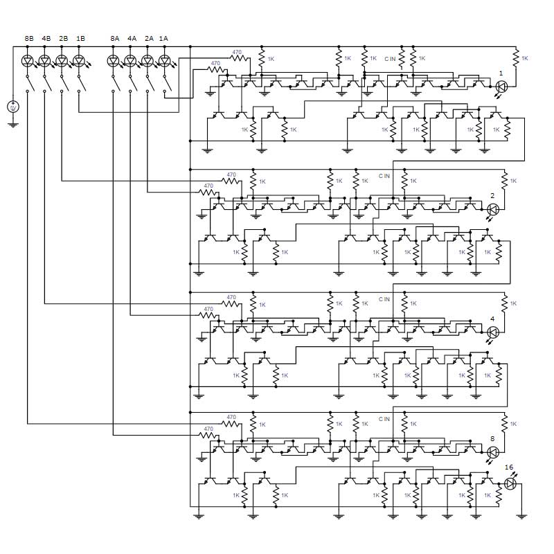
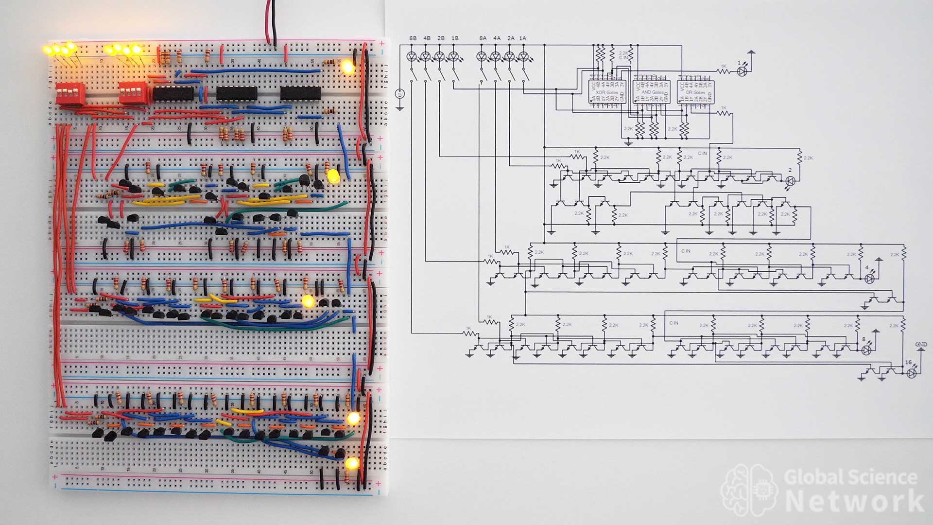
Component Level Circut Diagram
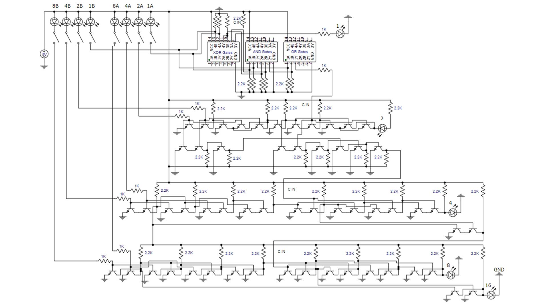
The circuit diagram above provides a detailed depiction of where every connection should be made to build the 4-bit calculator. Each full adder is built differently but the input and outputs are equal. This is an interesting way to build a 4-bit calculator cause it also demonstrates how to build six types of logic gates and shows how to implement integrated circuits. It takes around 20 hours of work to build a 4-bit calculator using individual transistors. This is because it is time-consuming to place all the components and cut the wires to the correct size. If you do build one of these calculators it is a useful way to teach others how logic gates work and how the ALU in a computer functions.
Now that you understand how to build a 4-bit calculator. Check out the video above where I build a 4-bit computer on breadboards. The ALU merged the two calculators above and added in XOR gates to allow subtraction using the 2’s complement method.
Cody started the Global Science Network with the idea people should be focusing more time, energy, and resources on useful projects. He has a bachelor’s degree in aerospace engineering and a master’s degree in mechanical engineering. Cody has worked for the US federal government, a university, a large corporation, small businesses, and for himself. He has done human brain computer interface research and is currently working towards creating non-biological human consciousness.
4-Bit Computer Built on Breadboards Using Individual Transistors
To learn how computers work it is helpful to build a simple computer. This 4-bit computer is built on 32 breadboards and uses 962 NPN BJT transistors. It is powered by a 5-volt rechargeable battery pack and uses about 1 AMP of current. Other components used include resistors LEDs, capacitors, and 22 gauge wires. It is awesome that a functional computer can be built using only these discrete electrical components.
The photo above shows the completed computer. When operating the computer can add or subtract values up to 15. It can hold seven operational commands and store three values to load A, add, or subtract.
The video above describes exactly how the full computer works. I would highly recommend watching the entire video.
When the computer was about half finished I made the video above. The computer is actually functional however the registeres, databus, and ALU signals need to be controlled manually. This is actually a very helpful way to show exactly how information is being sent around the computer and performing mathematical operations.

A complete logic gate-level circuit diagram of the 4-bit computer is shown above. Sections of the computer include the clock, program counter, ring counter, opcode register, opcode decoder, control matrix, data bus, 10 bytes of 4-bit memory, accumulator register, output register, register B, and the arithmetic logic unit which is also called the ALU.
Computer Clock
The computer clock is built with an a-stable multi-vibrator. This circuit produces an even square wave where the output signal is either on or off. It is built with four transistors and two 10 microfard capacitors. In the video, the clock is completing a full cycle once every 1.75 seconds. The clock rate can be increased significantly higher than this but to see how the computer works this is a good clock rate.
Program Counter
In most computers, the program counter is a binary counter which is shown in the video below. For the 4-bit computer, it was easier to have the program counter be a 7-stage ring counter. This is because if a binary counter was used the memory module would have had to decode the binary number into individual signals. The ring counter already has the individual signals as the default output.
Ring Counter
The 7-stage ring counter was built with four edge-triggered data flip flops. Each trigger is built with a 330 picofarad capacitor and a 1K resistor. Each time the clock completes one full cycle the ring counter increments. The output of the ring counter goes to the control matrix and enables when information will be sent to different parts of the computer.
Opcode Register
Information is sent from the memory module into the opcode register where this value gets latched. Once the data is latched it is continuously being sent into the opcode decoder. The opcode register gets enabled from a control signal coming from the control matrix.
Opcode Decoder
A binary value is continuously being sent from the opcode register into the opcode decoder. Using inverters and multiple input NAND gates the opcode decoder turns the binary value into a single on output which represents load A, add, subtract, output, and halt commands. These commands get sent into the control matrix to control when circuits in the computer are enabled.
Control Matrix
Signals from the ring counter and opcode decoder are sent to the control matrix. Depending on the values of these signals will determine the output of the control matrix. Circuits in the control matrix are inverters or multiple input NAND gates.
Data Bus
The data bus allows signals to be connected from one circuit to another. Only one circuit should be sending data to the data bus at one time. By default, the data bus has all the data lines on. This is because pull-up resistors are connected from positive 5-volts to each data line. When a circuit connects to the data bus it actually just grounds the data lines that should be off. This makes it so the proper value is on the data bus. When no circuits are connected to the data bus all the data lines are on. There are four other lines of the data bus which include ground, positive 5 volts, the clock signal, and clear. When the clear line is connected to ground it sets the counters to 1 and the output register to zero.
10 Bytes of 4-Bit Memory
The memory module consists of the memory display with buffers and 10 bytes of memory. When memory is being sent to the data bus the display will show which byte is being sent. Each byte of memory is hard coded based on whether resistors are connected to positive or ground. If the resistor is connected to the ground it is on and it if is connected to 5 volts it is off. This is because each byte is connected to the data bus via simplified tri-site buffers which invert the value. The first seven bytes of memory store the opcode instructions, byte 8 contains the load A value, byte 9 is the add value, and byte 10 holds the subtract value.
Accumulator Register
Data is sent to the accumulator register via the data bus. These values get latched in the master-slave data flip-flop and are continuously being sent into the ALU. During the 5 and 6 stages of the ring counter cycle, the value for the ALU will be sent to the data bus and latched into the accumulator register. This makes it so the value the ALU computes can be used in the next ring counter cycle.
Output Register
The output register is made with four regular data flip-flops. When the entire program is complete the final value gets latched into the output register. How this computer is built the output is displayed on LEDs but does not get sent to other circuits.
Register B
Data gets sent from the memory module to the data bus to get latched in register B. Once the value gets latched it is continuously being sent into the ALU. Each bit value gets latched into a regular data flip-flop. This register is built very similarly to register B.
Arithmetic Logic Unit, ALU
The ALU allows the computer to add and subtract numbers up to 15. This is done by using four full adders and four XOR subtract gates. Data is sent into the ALU from the accumulator register and register B. The output is displayed on LEDs and is sent to the data bus via tri-state buffers.
Most people are familiar with the base 10 number system. Computers operate using the base two number system which is also called binary. The video above shows how computers add numbers by using a 4-bit calculator I built on breadboards. If you watch this you will have a good understanding of how the ALU of the computer works.
This video shows how to build a 4-bit calculator using individual transistors. Four full adders are built to be able to add numbers up to 31 as the output has 5-bits.
Final Thoughts
Building a transistor computer on breadboards helps explain how a computer works. It also helps teach logic gate circuit design, data flip-flop design, and how to build each circuit of the computer. If I tried to build the processor in my current personal computer which has about 3 billion transistors it would take about 100 million breadboards to build. This computer also has 32 GB of RAM which has around 35 billion transistors, the 8GB NVIDIA GPU has around 7 billion transistors, and the 1 TB SSD has around 3 trillion transistors. So clearly this could not be built on breadboards.
However, when computers were first being built they were much larger than this breadboard computer. As technology progressed transistors and computers were able to be built much smaller. My next goal is to build artificial neurons. At first, they will be large and bulky but eventually, we should be able to build billions of neurons and trillions of synapses on a very small silicon or carbon substrate.
Cody started the Global Science Network with the idea people should be focusing more time, energy, and resources on useful projects. He has a bachelor’s degree in aerospace engineering and a master’s degree in mechanical engineering. Cody has worked for the US federal government, a university, a large corporation, small businesses, and for himself. He has done human brain computer interface research and is currently working towards creating non-biological human consciousness.